AT-SBx908 GEN2 Installation Guide for Virtual Chassis Stacking
41
Stacking Guidelines
Here are general stacking guidelines:
A stack can have two, three, or four switches.
Stacking requires v5.4.8-0.2 or later of the AlliedWare Plus
management software. Instructions later in this guide explain how
to view the version number of the operating software on the
switches.
The VCStack feature comes standard with the AlliedWare Plus
operating software. No additional software or license is required.
The default setting for the VCStack feature on the AT-SBx908
GEN2 Switch is disabled. Enabling it requires rebooting the switch.
Instructions later in this guide explain how to enable the feature
and reboot the unit.
All the switches in a stack must have the same optional features
licenses. If you purchased optional features, you should install
them on the switches before assembling the stack.
The switches of a stack are connected with a physical network link called a
stack trunk. Here are the trunk guidelines:
Trunk ports can be 10Gbps, 40Gbps, or 100Gbps.
There are no default trunk ports.
A stack can have only one trunk, but, as explained here, a trunk
can have more than one network link.
You designate trunk ports with the STACKPORT command in the
AlliedWare Plus operating system.
Trunk ports can be on any AT-XEM2 Line Card in any card slot in
the chassis. This differs from other stacking products where trunk
ports are usually pre-defined.
You cannot view or change the parameter settings of trunk ports.
If you are using fiber optic transceivers for the trunk, the
transceivers must be from Allied Telesis. Transceivers from other
network equipment providers might not operate properly as part of
a trunk link. For a list of supported transceivers, refer to the Allied
Telesis web site.
A stack of AT-SBx908 GEN2 Switches cannot contain other
stacking products, such as x600 or x610 Series switches.
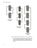
Figure 9 on page 42 illustrates the basic trunk configurations for
stacks of two, three, or four switches. The example shows the AT-
XEM2-4QS Line Card, but the topology is the same for all line
cards.
Summary of Contents for AT-FAN08
Page 10: ...Figures 10...
Page 12: ...Tables 12...
Page 16: ...Preface 16...
Page 38: ...Chapter 1 Overview 38...
Page 60: ...Chapter 2 Virtual Chassis Stacking 60...
Page 82: ...Chapter 4 Installing the Chassis 82 Figure 34 Example of Adjusting the Equipment Rack Brackets...
Page 104: ...Chapter 4 Installing the Chassis 104...
Page 140: ...Chapter 5 Powering On the Chassis 140...
Page 166: ...Chapter 7 Cabling the AT XEM2 Line Card Ports 166...

