Chapter 5: Powering On the Chassis
110
Powering On AT-SBxPWRSYS1-80 DC Power Supplies
The procedure in this section explains how to power on AT-
SBxPWRSYS1-80 DC Power Supplies. If you have not installed the power
supplies, refer to “Installing AT-SBxPWRSYS1-80 DC Power Supplies” on
page 91 for instructions.
Before powering on the chassis, review the information in “Power
Specifications” on page 209 for the power specifications of the switches.
The power supply unit has a ground connection and positive and negative
DC terminals. You may install the ground and power lead wires with the
terminal lugs that come with the unit or with bare wire. The wire
requirements are slightly different for terminal installation versus bare wire
installation. Here are the wire requirements if you are using the terminals
that come with the power supply:
Two 8 AWG stranded power wires (not provided)
One 10 AWG stranded grounding wire (not provided)
Here are the wire requirements for bare wire installation:
Two 8 AWG solid or stranded power wires (not provided)
One 10 AWG solid or stranded grounding wire (not provided)
Here is a list of the required tools:
Crimping tool (not provided)
8 mm wrench (not provided)
#1, #2, and #3 Phillips-head screwdrivers (not provided)
#3 Phillips-head 30 to 40 inch-lbs Phillips-head torque screwdriver
(optional - not provided)
Here are the procedures for powering on AT-SBxPWRSYS1-80 DC Power
Supplies:
“Choosing a Method for Attaching the Grounding Wire” on page 112
“Connecting the Grounding Wire with the Grounding Terminal” on
page 112
“Connecting the Grounding Wire with Bare Wire” on page 117
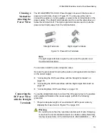
“Choosing a Method for Attaching the Power Wires” on page 119
“Connecting the DC Power Wires with the Straight Terminals” on
page 119
“Connecting the DC Power Wires with the Right Angle Terminals” on
page 127
Summary of Contents for AT-FAN08
Page 10: ...Figures 10...
Page 12: ...Tables 12...
Page 16: ...Preface 16...
Page 38: ...Chapter 1 Overview 38...
Page 60: ...Chapter 2 Virtual Chassis Stacking 60...
Page 82: ...Chapter 4 Installing the Chassis 82 Figure 34 Example of Adjusting the Equipment Rack Brackets...
Page 104: ...Chapter 4 Installing the Chassis 104...
Page 140: ...Chapter 5 Powering On the Chassis 140...
Page 166: ...Chapter 7 Cabling the AT XEM2 Line Card Ports 166...


