AT-SBx908 GEN2 Installation Guide for Virtual Chassis Stacking
127
Connecting the
DC Power Wires
with the Right
Angle Terminals
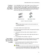
To use the right angle terminals to connect the DC power wires to the
positive and negative terminals on the AT-SBxPWRSYS1-80 DC Power
Supply, perform the following procedure:
1. Prepare adequate lengths of two stranded 8 AWG power wires by
stripping them as shown in Figure 75 on page 120.
Warning
Do not strip more than the recommended amount of wire. Stripping
more than the recommended amount can create a safety hazard by
leaving exposed wire on the terminal block after installation.
E10
Note
You must use stranded wires with the terminal lugs. You may not
use solid wires.
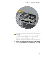
2. Insert the power wires into the terminals included with the power
supply and use a crimping tool to secure the wires to the terminals.
See Figure 83.
Figure 83. Attaching the Power Wires to the Right Angle Terminal Lugs
3. Verify that the On/Off switch on AT-SBxPWRSYS1-80 DC Power
Supply is in the Off position. Refer to Figure 67 on page 113.
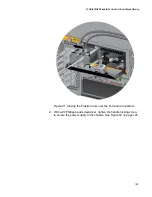
4. Using a #1 Phillips-head screwdriver, remove the two screws that
secure the plastic cover over the positive and negative terminals and
remove the plastic cover from the power supply, as shown in Figure 84
on page 128. You may need to lift the locking handle slightly to access
the bottom screw.
Summary of Contents for AT-FAN08
Page 10: ...Figures 10...
Page 12: ...Tables 12...
Page 16: ...Preface 16...
Page 38: ...Chapter 1 Overview 38...
Page 60: ...Chapter 2 Virtual Chassis Stacking 60...
Page 82: ...Chapter 4 Installing the Chassis 82 Figure 34 Example of Adjusting the Equipment Rack Brackets...
Page 104: ...Chapter 4 Installing the Chassis 104...
Page 140: ...Chapter 5 Powering On the Chassis 140...
Page 166: ...Chapter 7 Cabling the AT XEM2 Line Card Ports 166...


