Chapter 7: Cabling the AT-XEM2 Line Card Ports
160
Installing and Cabling Fiber Optic Transceivers
Table 15 lists the types of fiber optic transceivers that are supported by the
AT-XEM2 line cards. Refer to the product datasheet for a list of approved
transceivers.
Please review “Guidelines to Handling Twisted Pair or Fiber Optic
Transceivers” on page 159 before performing the procedure.
Your transceivers may look different than those shown in the following
illustrations.
Warning
The temperature of an operational transceiver can exceed 70° C
(158° F). Exercise caution when removing or handling transceivers
with unprotected hands.
E43
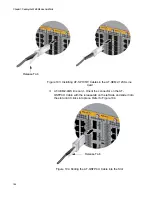
To install a fiber optic transceiver in an Ethernet line card, perform the
following procedure:
1. Select a slot in the AT-XEM2 line card for the transceiver.
2. If the selected slot has a dust cover, remove it.
3. Remove the transceiver from its shipping container and store the
packaging material in a safe location.
4. Orient the transceiver and slide it into the slot until it clicks into place.
The correct orientation depends on the line card and transceiver:
AT-XEM2-12XS Line Card - To install a transceiver in an odd
numbered slot, position its handle on the right. To install a
transceiver in an even numbered slot, position its handle on the
left. Refer to Figure 100 on page 161.
Table 15. AT-XEM2 Line Cards and Fiber Optic Transceivers
Ethernet Line Card
Fiber Optic Transceiver
AT-XEM2-12XS
1Gbps SX or LX SFP
10Gbps SR or LR SFP
AT-XEM2-4QS
40Gbps QSFP+
AT-XEM2-1CQ
100Gbps SR or LR QSFP28
Summary of Contents for AT-FAN08
Page 10: ...Figures 10...
Page 12: ...Tables 12...
Page 16: ...Preface 16...
Page 38: ...Chapter 1 Overview 38...
Page 60: ...Chapter 2 Virtual Chassis Stacking 60...
Page 82: ...Chapter 4 Installing the Chassis 82 Figure 34 Example of Adjusting the Equipment Rack Brackets...
Page 104: ...Chapter 4 Installing the Chassis 104...
Page 140: ...Chapter 5 Powering On the Chassis 140...
Page 166: ...Chapter 7 Cabling the AT XEM2 Line Card Ports 166...


