background image

PN 613-001687 Rev. A

AT-GS900/8PS

Gigabit Ethernet POE+ Switch

AT-GS900/8PS Installation Guide 

Summary of Contents for AT-GS900/8PS

Page 1: ...PN 613 001687 Rev A AT GS900 8PS Gigabit Ethernet POE Switch AT GS900 8PS Installation Guide...

Page 2: ...espective owners Allied Telesis Inc reserves the right to make changes in specifications and other information contained in this document without prior written notice The information provided herein i...

Page 3: ...s uses and can radiate radio frequency energy and if not installed and used in accordance with this instruction manual may cause harmful interference to radio communications Operation of this equipmen...

Page 4: ...Safety Statements Important The indicates that a translation of the safety statement is available in a PDF document titled Translated Safety Statements posted on the Allied Telesis website at www alli...

Page 5: ...s 22 Power Over Ethernet 25 PoE Standards 25 PoE Powered Device Classes 26 PoE Power Budget 26 PoE Port Prioritization 27 PoE Guard Band 27 Exceeding PoE Power Budget 27 Wiring Implementation 29 Power...

Page 6: ...ce Not Receiving Power 50 Resetting Blinking PoE Port LED 51 Appendix A Technical Specifications 53 Physical Specifications 53 Environmental Specifications 53 Power Specifications 53 PoE Specification...

Page 7: ...to the Switch 38 Figure 7 Mounting the Switch in an Equipment Rack 39 Figure 8 Attaching the Brackets to Install the Switch on a Wall 40 Figure 9 Marking the Screw Hole Locations 41 Figure 10 Securing...

Page 8: ...Figures 8...

Page 9: ...e 6 IEEE Powered Device Classes 26 Table 7 Physical Specifications 53 Table 8 Environmental Specifications 53 Table 9 Power Specifications 53 Table 10 PoE Specifications 54 Table 11 Safety and Electro...

Page 10: ...Tables 10...

Page 11: ...This guide contains the installation instructions for the AT GS900 8PS Gigabit Ethernet POE Switch This preface contains the following sections Symbol Conventions on page 12 Contacting Allied Telesis...

Page 12: ...Cautions inform you that performing or omitting a specific action may result in equipment damage or loss of data Warning Warnings inform you that performing or omitting a specific action may result i...

Page 13: ...bout RMAs and contact Allied Telesis technical experts USA and EMEA phone support Select the phone number that best fits your location and customer type Hardware warranty information Learn about Allie...

Page 14: ...Preface 14...

Page 15: ...T GS900 8PS Layer 2 Gigabit Ethernet Switch The sections in the chapter are Features on page 16 Front and Back Panels on page 18 Twisted Pair Ports on page 19 SFP Port on page 21 LEDs on page 22 Power...

Page 16: ...ng distance IEEE 802 3x flow control in 10 100Base TX full duplex operation IEEE 802 3x back pressure in 10 100Base TX half duplex operation IEEE803 3z 1000Base T flow control LEDs Speed and link acti...

Page 17: ...abletop Wall Power Conservation High efficiency internal power supply Power scaling based on traffic loads on ports operating at 1000 Mbps and cable length port power scaling not available at 10 or 10...

Page 18: ...he front panel of the AT GS900 8PS Gigabit Ethernet Switch Figure 1 AT GS900 8PS Front Panel The switch back panel is illustrated in Figure 2 Figure 2 Back Panel Port 10 100 1000Base T Twisted Pair Po...

Page 19: ...or MDI X when it is connected to an end node Consequently you can use a straight through or cross over twisted pair cable when connecting any type of network device to a port on the switch MDI MDI X M...

Page 20: ...mode uses PAUSE frames as specified in the IEEE 802 3x standard to momentarily stop the transmission of data from an end node Whenever a switch port wants an end node to stop transmitting data because...

Page 21: ...ort Port 9 This port is capable of supporting one 1000SX LX SFP module Refer to the AT GS900 8PS product data sheet for information concerning the specific SFP models supported and fiber cable specifi...

Page 22: ...the Power over Ethernet PoE LEDs Table 2 System LED LED State Description POWER Solid Green The input AC power is within the normal operating range Off The switch is not receiving AC power Table 3 Pow...

Page 23: ...s required so the total PoE power delivered is less than 75 W Off Total PoE power delivered is below 70W Table 4 10 100 1000Base T Port LEDs LED State Description L A link activity Steady Green The po...

Page 24: ...ty Solid Green The SFP transceiver has established a link with a network device but is not transmitting or receiving network packets Blinking Green The SFP transceiver is transmitting or receiving net...

Page 25: ...00 8PS switch acts as a PSE unit by adding DC power to the network cable thus functioning as a central power source for another network device Devices that receive their power from a PSE are called po...

Page 26: ...ore ports using a mechanism referred to as port prioritization To determine whether the power requirements of the PoE devices you plan to connect to the switch exceed its power budget refer to the doc...

Page 27: ...switch ports This power band is reached when the total PoE power requirements of all of the powered devices connected to the switch fall into this range It is indicated on the front panel when the Po...

Page 28: ...Chapter 1 Overview 28 Note To reset a blinking PoE port LED see Resetting Blinking PoE Port LED on page 51 Note In addition a blinking POE LED can indicate that a PoE port has a short circuit...

Page 29: ...of eight strands With 10Base T and 100Base TX devices the strands connected to pins 1 2 3 and 6 on the RJ 45 connectors carry the network traffic while strands connected to pins 4 5 7 and 8 are unuse...

Page 30: ...single AC power supply socket on the back panel and autoswitch AC inputs To power the switch on or off connect or disconnect the power cord provided with the switch A power cord is supplied with the s...

Page 31: ...a Site for the Switch on page 34 Unpacking the Switch on page 35 Installing the Switch on a Desktop on page 37 Installing the Switch in an Equipment Rack on page 38 Installing the Switch on a Wall on...

Page 32: ...ectric shock disconnect electric power to the product before connecting or disconnecting the cables E1 Warning Do not work on equipment or cables during periods of lightning activity E2 Warning Power...

Page 33: ...hould be such that a hazardous condition is not created due to uneven mechanical loading E25 If installed in a closed or multi unit rack assembly the operating ambient temperature of the rack environm...

Page 34: ...et for the switch should be located near the unit and should be easily accessible The site should provide for easy access to the ports on the front of the switch This will make it easier for you to co...

Page 35: ...h perform the following procedure 1 Remove all of the components from the shipping package Note Store the packaging material in a safe location You must use the original shipping material if you need...

Page 36: ...tch Items Two equipment brackets for wall or rack installation Eight bracket screws for wall or rack installation Four wall anchors for wall mount installation Four screws and washers for wall mount i...

Page 37: ...the following procedure 1 Remove all equipment from the package and store the packaging material in a safe place 2 Turn the switch over and place it on a table 3 Attach the four rubber feet to the bo...

Page 38: ...ottom of the switch remove them using a flat head screwdriver 2 Attach the two rack mount brackets to the sides of the switch using the eight bracket screws that are provided There are four possible p...

Page 39: ...AT GS900 8PS Switch Installation Guide 39 Figure 7 Mounting the Switch in an Equipment Rack 4 Go to Installing Optional SFP Transceiver on page 43 or Cabling the Switch on page 45...

Page 40: ...sides of the switch as shown in Figure 8 and secure them to the unit with the eight bracket screws included with the switch Figure 8 Attaching the Brackets to Install the Switch on a Wall 4 Have anot...

Page 41: ...ic anchors included with the switch into the wall at the locations marked in the previous step The anchors require 0 635 mm 0 25 in holes 6 While another person holds the switch at the wall location s...

Page 42: ...Chapter 2 Installation 42 Figure 10 Securing the Switch to the Wall 7 Go to Installing Optional SFP Transceiver on page 43 or Cabling the Switch on page 45...

Page 43: ...er always remove the cables from the transceiver before removing it 1 Remove the transceiver from its shipping container and store the packaging material in a safe location Warning An SFP transceiver...

Page 44: ...switch This secures the transceiver and prevents it from being dislodged from the slot Note SFP transceivers are dust sensitive Always keep the protective plug in the optical bore when a fiber optic...

Page 45: ...ed The cable connector should fit snugly into the port on the switch The tab on the connector should lock the connector into place Because the twisted pair ports have auto MDI MDI X you may use straig...

Page 46: ...d 2 Plug the other end of the power cord into a wall outlet 3 Verify that the POWER LED is green If the LED is OFF refer to Chapter 3 Troubleshooting on page 47 The switch is now powered on and ready...

Page 47: ...liedtelesis com support Power LED OFF Problem The POWER LED on the front of the switch is off Solutions The unit is not receiving power Try the following Verify that the power cord is securely connect...

Page 48: ...tegory 5E for 100 and 1000 Mbps operation Note A 1000Base connection may require five to ten seconds to establish a link SFP Port LINK ACT LED Off Problem The LINK ACT LED for an SFP transceiver is of...

Page 49: ...work device Since the AT GS900 8PS copper ports are always configured for Auto Negotiation they will default to half duplex mode if the corresponding link partner is configured for a fixed duplex mode...

Page 50: ...t indicates one of the following problems There may be a short circuit in the Ethernet cable You can verify that the Ethernet cable does not have a short by replacing it with a cable that you know is...

Page 51: ...wer off by disconnecting the AC power cord 2 If the total PoE power from all the powered devices connected to the switch is greater than 70 W reduce the total PoE load until it is less than 70 W 3 If...

Page 52: ...Chapter 3 Troubleshooting 52...

Page 53: ...sions H x W x D 280 mm x 180 mm x 44 mm 11 0 in x 7 1 in x 1 7 in Weight 1 52 kg 3 35 lbs Table 8 Environmental Specifications Operating Temperature 0 C to 40 C 32 F to 113 F Storage Temperature 25 C...

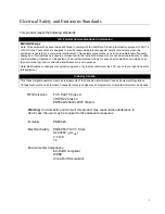
Page 54: ...Lowest Standard Supports both IEEE 802 3at and IEEE 802 3af Mode Alternate A Max Power Limit per port 30W Max Power Limit 75W PoE Guard Band 70W to 75 W Table 11 Safety and Electromagnetic Emissions...

Page 55: ...RJ 45 Connector and Port Pin Layout Table 12 lists the RJ 45 pin signals when a twisted pair port is operating in the MDI configuration Table 13 lists the RJ 45 port pin signals when a twisted pair p...

Page 56: ...J 45 connector pins and their signals when a 1000Base T port is operating at 1000 Mbps Table 14 RJ 45 1000Base T Connector Pinouts Pin Pair Signal 1 1 TX and RX 2 1 TX and RX 3 2 TX and RX 4 3 TX and...

Reviews: