PowerBlade PBC18 Quick Install Guide
11
4.
For an AC powered unit, plug one end of the power cord to the back of the
power supply and plug the other end to a power outlet. Proceed to Step 6
on page 13 for further instructions.
Note
If you purchased an optional management module, install the module
before applying power to the chassis. Refer to “Installing an Optional
Management Module” on page 27 for instructions.
5.
For a DC powered unit, perform the following steps:
a. Before attaching wires to the DC terminal block on the power module,
review the following warning:
Warning
As a safety precaution, a 10 Amp circuit breaker should be installed at
the supply end of the cable to be used with this LAN equipment.
Always connect the wiring to the LAN equipment first before
connecting the wiring to the breaker. To avoid the danger of physical
injury from electrical shock, do not work with hot feeds. Always be sure
that the breaker is in the OFF position before connecting the wiring to
the breaker.
!
16
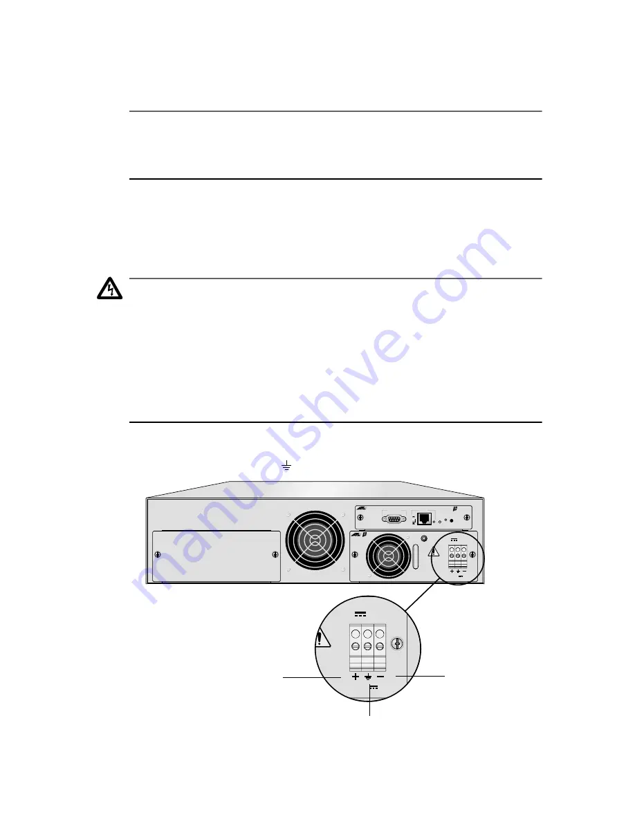
b. Identify the positive, frame ground and negative terminals using
the positive (+), ground (
), and negative (-) symbols.
Figure 7 Positive, Ground, and Negative Symbols
PWR 2
PWR 1
PBM02
Management
MDI-X
MDI
LNK
STATUS
PWR
RESET
RS-232 Terminal
10Base-T
PBPWRDC
FOR CENTRALIZED DC
POWER CONNECTION,
INSTALL ONLY IN A
RESTRICTED AREA
36-60VDC , 1.0A
DC INPUT
TRALIZED DC
CONNECTION,
L ONLY IN A
CTED AREA
36-60VDC , 1.0A
DC INPUT
Positive
Ground
Negative


