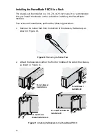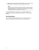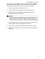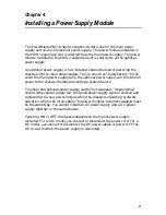
28
Installing an Optional Management Module
To install an optional management module, perform the following procedure:
Warning
Installing an optional management module while the chassis is powered
ON could result in damage to the module.
1.
Power OFF the chassis by performing one of the following:
❑
For an AC model, unplug the power cord from the power outlet and
then unplug the power cord from the chassis.
❑
For a DC model, follow the steps below:
Warning
When installing this equipment, always ensure that the frame ground
connection is installed first and disconnected last.
!
18
a. Remove the positive and negative feed wires from the terminal block
by loosening the screws to the wire connection with a flathead
screwdriver.
b. Remove the frame ground wire from the terminal block by loosening
the screw to the wire connection with a flathead screwdriver.
2.
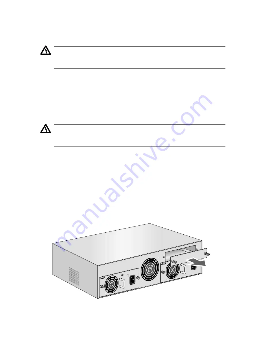
Remove the blank faceplate covering the management module expansion
slot by loosening the two thumbscrews. See Figure 22.
Figure 22 Removing the Management Module Blank Faceplate
PWR 2
PWR 1
PBPWRA
C
AC IN
PUT
100-2
40AC
50-60
Hz
3A MA
X.
150W
PBPWRA
C
AC INPU
T
100-2
40AC
50-60
Hz
3A MA
X.
150W

