x310 Series Installation Guide for Stand-alone Switches
21
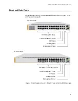
The back panel of the AT-x310-26FT Switch is shown in Figure 3.
Figure 3. Back Panel of the AT-x310-26FT Switches
The back panel of the AT-x310-26FP and AT-x310-50FP Switches is
shown in Figure 4.
Figure 4. Back Panel of the AT-x310-26FP and AT-x310-50FP Switches
The back panel of the AT-x310-50FT Switch is shown in Figure 5.
Figure 5. Back Panel of the AT-x310-50FT Switch
AC Power
Connector
AC Power Connector
AC Power Connector
Summary of Contents for AT-x310-26FP
Page 10: ...Tables 10 ...
Page 14: ...Preface 14 ...
Page 46: ...Chapter 1 Overview 46 ...
Page 56: ...Chapter 2 Beginning the Installation 56 ...
Page 92: ...Chapter 5 Cabling the Networking Ports 92 ...

