x310 Series Installation Guide for Stand-alone Switches
69
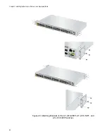
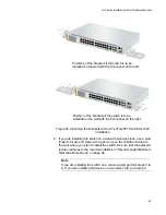
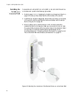
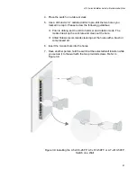
Figure 26. Attaching the Brackets to the AT-x310-26FT Switch for Wall
Installation
4. If you are installing the switch on a wall with wooden studs, use a stud
finder to locate and mark with a pencil or pen the middle of a stud in
the wall where you plan to install the switch. Be sure that the selected
location adheres to the recommendations in “Recommended Minimum
Wall Area Dimensions” on page 66.
Note
If you are installing the switch on a concrete wall, perform steps 5 to
8. If you are installing the device on a wooden stud, go to step 9.
Positions of the brackets if the switch is to be
installed on the wall with the front panel on the left.
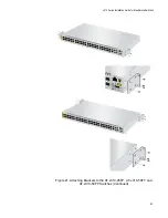
Position of the brackets if the switch is to be
installed on the wall with the front panel on the right.
Summary of Contents for AT-x310-26FP
Page 10: ...Tables 10 ...
Page 14: ...Preface 14 ...
Page 46: ...Chapter 1 Overview 46 ...
Page 56: ...Chapter 2 Beginning the Installation 56 ...
Page 92: ...Chapter 5 Cabling the Networking Ports 92 ...


