7
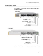
Figure 1: Front Panels of the AT-x310-26FT and AT-x310-26FP Switches ......................................................................... 19
Figure 2: Front Panels of the AT-x310-50FT and AT-x310-50FP Switches ......................................................................... 20
Figure 3: Back Panel of the AT-x310-26FT Switches........................................................................................................... 21
Figure 4: Back Panel of the AT-x310-26FP and AT-x310-50FP Switches ........................................................................... 21
Figure 5: Back Panel of the AT-x310-50FT Switch............................................................................................................... 21
Figure 6: x310 Series Management Panel ........................................................................................................................... 22
Figure 7: AT-StackXS/1.0 Stacking Transceiver .................................................................................................................. 33
Figure 8: LEDs for the 10/100Mbps Ports on the AT-x310-26FT and AT-x310-50FT Switches........................................... 35
Figure 9: LEDs for the PoE 10/100Base-TX Ports on the AT-x310-26FP and AT-x310-50FP Switches ............................. 37
Figure 10: LEDs for the 10/100/1000Base-T Ports............................................................................................................... 39
Figure 11: SFP Slot LEDs .................................................................................................................................................... 40
Figure 12: Switch ID LED ..................................................................................................................................................... 41
Figure 13: Switch ID LED ..................................................................................................................................................... 42
Figure 14: Switch ID LEDs in the Low Power Mode ............................................................................................................. 42
Figure 15: Components of the Switches............................................................................................................................... 53
Figure 16: Components of the AT-x310-26FT Switch ..........................................................................................................54
Figure 17: Turning the Switch Upside Down ........................................................................................................................ 60
Figure 18: Removing the Rubber Feet ................................................................................................................................. 60
Figure 19: Installing Brackets on the AT-x310-26FT Switch................................................................................................. 61
Figure 20: Attaching Brackets to the AT-x310-26FP, AT-x310-50FT, and AT-x310-50FP Switches ................................... 62
Figure 21: Attaching Brackets to the AT-x310-26FP, AT-x310-50FT, and AT-x310-50FP Switches (Continued) ............... 63
Figure 22: Mounting the Switch in an Equipment Rack ........................................................................................................ 64
Figure 23: Positions of the AT-x310-26FT Switch on a Wall ................................................................................................ 66
Figure 24: Minimum Wall Area Dimensions for the AT-x310-26FT Switch with the Front Panel on the Left........................ 67
Figure 25: Minimum Wall Area Dimensions for the AT-x310-26FT Switch with the Front Panel on the Right ..................... 67
Figure 26: Attaching the Brackets to the AT-x310-26FT Switch for Wall Installation ........................................................... 69
Figure 27: Marking the Locations of the Bracket Holes on a Concrete Wall ........................................................................ 70
Figure 28: Installing the AT-x310-26FT Switch on a Wall..................................................................................................... 71
Figure 29: Positions of the AT-x310-26FP, AT-x310-50FT, and AT-x310-50FP Switches on a Wall................................... 73
Figure 30: Minimum Wall Area Dimensions for the Switch When the Front Panel is on the Left ......................................... 74
Figure 31: Minimum Wall Area Dimensions for the Switch When the Front Panel is on the Right....................................... 74
Figure 32: Bracket Positions on the Switch .......................................................................................................................... 75
Figure 33: Switch on a Plywood Base .................................................................................................................................. 76
Figure 34: Distances Between the Brackets on the AT-x310-26FP, AT-x310-50FT, and AT-x310-50FP Switches ............ 77
Figure 35: Steps to Installing the Switch with a Plywood Base ............................................................................................78
Figure 36: Attaching the Brackets for Wall Installation for All Switches Except the AT-x310-26FT Switch.......................... 80
Figure 37: Securing the Switch to the Plywood Base ........................................................................................................... 81
Figure 38: Marking the Locations of the Bracket Holes on a Concrete Wall ........................................................................ 82
Figure 39: Installing the AT-x310-26FP, AT-x310-50FT, or AT-x310-50FP Switch on a Wall.............................................. 83
Figure 40: Removing the Dust Plug from an SFP Slot ......................................................................................................... 89
Figure 41: Installing an SFP Transceiver.............................................................................................................................. 89
Figure 42: Removing the Dust Cover from an SFP Transceiver .......................................................................................... 90
Figure 43: Positioning the SFP Handle in the Upright Position ............................................................................................90
Figure 44: Connecting a Fiber Optic Cable to an SFP Transceiver...................................................................................... 91
Figure 45: Installing the Retaining Clip ................................................................................................................................. 94
Figure 46: Raising the Retaining Clip ................................................................................................................................... 95
Figure 47: Plugging in the AC Power Cord........................................................................................................................... 95
Figure 48: Lowering the Retaining Clip................................................................................................................................. 95
Figure 49: Switch Initialization Messages............................................................................................................................. 97
Figures
Summary of Contents for AT-x310-26FP
Page 10: ...Tables 10 ...
Page 14: ...Preface 14 ...
Page 46: ...Chapter 1 Overview 46 ...
Page 56: ...Chapter 2 Beginning the Installation 56 ...
Page 92: ...Chapter 5 Cabling the Networking Ports 92 ...


