Chapter 5: Cabling the Networking Ports
90
Note
If you are ready to attach the fiber optic cable to the transceiver,
continue with the next step. Otherwise, repeat steps 1 to 4 to install
another SFP transceiver in the switch.
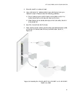
5. Remove the dust cover from the transceiver, as shown in Figure 42.
Figure 42. Removing the Dust Cover from an SFP Transceiver
6. Verify the position of the handle on the SFP transceiver. If the
transceiver is in a top slot, the handle should be in the upright position,
as shown in Figure 43. If the transceiver is in a bottom slot, the handle
should be in the down position.
Figure 43. Positioning the SFP Handle in the Upright Position
SFP Handle
Summary of Contents for AT-x310-26FP
Page 10: ...Tables 10 ...
Page 14: ...Preface 14 ...
Page 46: ...Chapter 1 Overview 46 ...
Page 56: ...Chapter 2 Beginning the Installation 56 ...
Page 92: ...Chapter 5 Cabling the Networking Ports 92 ...

