10
SwitchBlade 4000 Series Switch
C613-03060-00 REV H
Switching Performance and Characteristics
The SwitchBlade architecture is based on a non-blocking wire-speed Layer 2
and 3 switching fabric. Layer 3 switching is performed by line cards as well as
switch controllers. As with other Allied Telesis Layer 3 switches, the
SwitchBlade includes full multiprotocol routing capabilities.
Layer 3 switching performance is determined by the number of switch
controllers and line cards that are installed. If two switch controllers are
installed, each line card operates at maximum bandwidth. This provides
switching capacity of 192 Gbps for the 4 slot chassis, and 384 Gbps for the 8 slot
chassis. The 4 slot chassis can also achieve maximum bandwidth when one
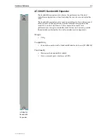
switch controller and a bandwidth expander (AT-SB4215) are installed.
Master Switch Controller and Slave Switch Controller
Interactions
The first switch controller to be installed in a chassis should be located in
switch controller bay A. This controller acts as the master switch controller,
performing all table updates and packet exception processing. Its “Master”
LED lights to confirm that it is the master switch controller.
When a second switch controller is installed, it is automatically designated
slave status. In this case the master still performs all table updates and packet
exception processing, but the switching load is shared between the two
controllers, while the slave maintains copies of the master’s routing tables.
Installing two switch controllers enables processing redundancy. If a switch
controller fails, or is removed, then the other controller assumes master status
and continues all processing operations. If the only operational controller is in
Bay B, then this will retain master status until an operational controller is
inserted in Bay A and a system reset or restart occurs.
Hot Swapping
Hot swapping is the replacement of a component (such as a line card) while the
switch is powered up. The following SwitchBlade components can be hot
swapped:
•
Power supply units (PSUs). The switch will continue to operate as long
as sufficient functional PSUs remain in place to meet the switch’s power
demand. “How Many PSUs do You Need?” on page 33 provides more
information on switch configurations and their power demands.
Note that only certain power supplies are fully hot swapable and that
this ability relates to the PSU being inserted, not the one being removed.
The following PSUs are fully hot swapable: AT-SB4162-V2 AC PSU, and
AT-SB4162-80 DC PSU.
•
Fan trays. Although the switch can operate for short periods without a
fan tray, such as while exchanging fan trays, it should not left running
for longer periods without a fan tray operating.
•
Switch controllers. The switch will continue to operate as long as at least
one functional switch controller (master or slave) remains in place,
although a brief pause in switching and routing may occur. Packets
passing through the switch during a switch-controller hot swap will be
lost.


