Hardware Reference
19
C613-03060-00 REV H
Mounting System
•
19 inch rack mounting
•
Front rack-mounting brackets incorporated in chassis. Mid or rear
mounting brackets optional
Expansion Bays
•
Two switch controller bays
•
Four line card bays
•
Two power supply bays
•
One fan tray bay (compatible with the AT-SB4151 fan tray)
Alarm Relays
•
Two relays on rear panel
•
Normally open and normally closed contacts
•
Software configurable for a range of conditions
•
See “
Alarm Relays and Monitoring
” on page 32 for more information
Backplane Links and Bus Connections
•
A SwitchBlade chassis contains two controller bays each capable of
housing a switch controller card. See “Switching Performance and
Characteristics” on page 10 for more information.
•
33 MHz 64 bit PCI routing and control bus links all switch controller
and line card bays. This bus provides a high performance
communication channel between switch controller CPUs, and also
allows high speed routing between line cards that have WAN
interfaces.
Earth/Ground Point
•
An earth/ground point is provided on the chassis’s rear panel. This
point can be used to bond the chassis to earth/ground. Even if this point
is used, earth/ground leads of AC and DC power supplies must still be
connected.
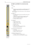
AT-SB4161 & 2 SwitchBlade Power Supply Units
For guidelines on how many PSUs are required for a particular configuration,
see “How Many PSUs do You Need?” on page 33.
LEDs
•
Three LEDs indicate power supply status (input, output, and fan status)
•
For a complete list of LEDs and their functions, see “LEDs and What
They Mean” on page 47
Power Supply Specifications
Weight
•
3.6 kg


