background image

50

SwitchBlade 4000 Series Switch

C613-03060-00 REV H

Check these first

1.

Check the power cord(s) connection(s).

2.

Check that the power supply voltage is stable.

3.

Check that the correct data cables are being used and that their connections 
are secure.

4.

Make sure that other network devices are working properly.

5.

Use the SHOW INSTALL command to check that the latest software version 
is loaded. See the 

SwitchBlade Software Reference

 for more information about 

obtaining the latest software version.

6.

If the switch is malfunctioning, reboot it by pressing the recessed Reset 
button or entering the command RESTART REBOOT. Alternatively, use the 
standby switch on the chassis’s rear panel to power OFF and ON the switch.

Some common problems and how to solve them

Link/Activity LED on any port is off

This can indicate:

A loose data cable.

The device at the other end of the connection is not working properly or is 
turned off.

The data cable is not wired correctly.

The network administrator has manually disabled the port through the 
software.

The port’s selected transmission mode does not match that of the attached 
device.

Perform the following steps in sequence:

1.

Make sure the data cable connections are secure.

2.

Make sure the device at the other end of the connection is switched on and 
working properly.

3.

Check that the data cable is wired correctly.

4.

If you can, log in and check the port status. See “To log In” on page 35 for 
more information on how to log in.

5.

If the port is Enabled, make sure the transmission speed matches that of the 
connected device (auto-negotiating, full or half-duplex).

If the port is disabled, someone has used the software to manually disable it. You should 
find out why the port was disabled before enabling it.

Power LED is off

This can indicate:

A loose power cord.

A power supply failure.

Perform the following steps in sequence:
Summary of Contents for SwitchBlade AT-SB4104-00

Page 1: ...SwitchBlade 4000 Series Switch Hardware Reference AT SB4108 00 AT SB4108 60 AT SB4108 80 AT SB4104 00 AT SB4104 80 ...

Page 2: ...ice The information provided herein is subject to change without notice In no event shall Allied Telesis Inc be liable for any incidental special indirect or consequential damages whatsoever including but not limited to lost profits arising out of or related to this manual or the information contained herein even if Allied Telesis Inc has been advised of known or should have known the possibility ...

Page 3: ... Ethernet Line Card 25 AT SB4412 and AT SB4412 V2 24 Port Gigabit RJ 45 Ethernet Line Card 26 AT SB4442 V2 24 Port Gigabit SFP Ethernet Line Card 28 AT SB4441 and AT SB4441 V2 8 GBIC Line Card 30 AT SB4541 V2 1 port 10GBASE R Gigabit Ethernet Line Card 31 Alarm Relays and Monitoring 32 Alarm Relays 32 Monitoring 33 How Many PSUs do You Need 33 Online Documentation 33 Accessing the CD ROM and Onlin...

Page 4: ...4 SwitchBlade 4000 Series Switch C613 03060 00 REV H Port Connector and Cable Combinations 58 Using Windows Terminal and Hyperterminal 59 Restricted Procedures 62 Diagnostics 62 Contacting Us 64 ...

Page 5: ...witchBlade 4 Fan Tray AT SB4211 Switch Controller AT SB4215 Bandwidth Expander AT SB4311 48 port 10BASE T 100BASE TX RJ 45 Line Card AT SB4352 32 port 100BASE FX MT RJ Line Card AT SB4412 24 port Gigabit RJ 45 Line Card AT SB4442 24 port 1000Base X SFP Line Card AT SB4441 8 port 1000BASE X GBIC Line Card AT SB4541 1 port 10GBASE LE XFP Line Card SwitchBlade Printed Acrobat PDF Website Documentatio...

Page 6: ... procedures For information on software refer to the SwitchBlade Software Reference Where to Find More Information The Documentation and Tools CD ROM bundled with each switch controller and chassis contains the complete document set for the switch and its expansion options as well as tools for managing the switch This includes the following SwitchBlade Safety Booklet Provides safety and statutory ...

Page 7: ...ds Line cards Provides layer 2 3 switching and the physical interfaces for connecting the cables fibre Additional line cards may be added to provide more ports and more port types than can be supplied by a single card Switch controller Provides advanced switching operations and configuration ports for the switch An additional switch controller may be added to increase speed and provide switch proc...

Page 8: ... AT SB4151 fan tray can only be used in the four slot chassis while the AT SB4152 fan tray can only be used in the eight slot chassis Power Feed Options The eight slot AC chassis is available with either triple AC power feeds or dual AC power feeds The eight slot DC chassis is only available with dual DC power feeds Eight Slot Triple Feed Models In these models each power feed connects only to its...

Page 9: ...DC power will then be provided via PSU 2 and PSU 3 Power Supplies The SwitchBlade chassis and power supplies offer a number of options such as hot swapping that provide varying degrees of resiliency and recovery See Power Feed Options on page 8 AT SB4161 2 SwitchBlade Power Supply Units on page 19 and How Many PSUs do You Need on page 33 DC GOOD FAN GOOD POWER PRESENT AT SB4162 AC POWER SUPPLY DC ...

Page 10: ...ween the two controllers while the slave maintains copies of the master s routing tables Installing two switch controllers enables processing redundancy If a switch controller fails or is removed then the other controller assumes master status and continues all processing operations If the only operational controller is in Bay B then this will retain master status until an operational controller i...

Page 11: ... as swapped out for this bay are replaced with new card interfaces A bay was previously occupied and the same card type is being hot swapped in The previous VLAN configuration for the card is restored to its previous condition and previous trunking settings are restored Interfaces registered against this card are marked up or down as appropriate Switch table entries are restored except for entries...

Page 12: ...card is retained including references to missing ports Card is hotswapped back in CREATE CONFIG executed No Yes Commands referring to missing ports fail on start up Switch remembers commands with failed ports When the dynamic configuration is displayed with SHOW CONFIG DYNAMIC missing commands show under Swapped out headings Switch restarted Card s configuration is restored to what it was before i...

Page 13: ...e cards within the range have been removed This limitation does not apply when a range of ports is entered into a command on the command line interface because the switch correctly splits the range when performing a create config command Examples The following examples describe possible scenarios where slots 1 and 2 are occupied by 8 port line cards and Line Card 1 is hot swapped out 1 Line Card 1...

Page 14: ...guration is vlan configuration add vlan v2 port 2 1 2 4 vlan swapped out port configuration add vlan v2 port 1 1 1 8 This situation is potentially problematic because the switch has been restarted before the line card was hot swapped back in The remaining examples describe possible ramifications 5 continuing from the end of Example 4 The switch is powered down and a different type of line card for...

Page 15: ...the swapped out configuration When the correct line card is inserted it is initialised without configuration To avoid loss of the swapped out configuration in this situation insert the correct line card and restart the SwitchBlade Then make the other configuration changes and create the configuration Physical and Operating Specifications This section provides an overview of the SwitchBlade s physi...

Page 16: ...y specified for the power supply AC models AT SB4108 00 Triple AC Feed 100 to 240 V AC 50 to 60 Hz input AT SB4108 60 Dual AC Feed 200 to 240 V AC 50 to 60 Hz input DC models 48 V DC Operating voltage range 40 to 60 V DC Accepts positive or negative earthing grounding LEDs System status LEDs on each switch controller Port LEDs on each line card Power supply status LEDs on each PSU and switch contr...

Page 17: ...ting and control bus links are present on all switch controller and line card bays This bus provides a high performance communication channel between switch controller CPUs and also allows high speed routing between line cards that have WAN interfaces Cable Management System Optional manager can be fitted to the fan tray front panel Cable manager supports up to four cable management loops Earth Gr...

Page 18: ...talled Consult your authorised Allied Telesis distributor or reseller for more information Note Because certain chassis models contain additional circuitry to control power supply switching the voltage ranges specified for the chassis can differ from those separately specified for the power supply AC models Universal 110 to 240 V AC 50 to 60 Hz input DC models 48 V DC 40 to 60 V DC operating range...

Page 19: ...on page 10 for more information 33 MHz 64 bit PCI routing and control bus links all switch controller and line card bays This bus provides a high performance communication channel between switch controller CPUs and also allows high speed routing between line cards that have WAN interfaces Earth Ground Point An earth ground point is provided on the chassis s rear panel This point can be used to bon...

Page 20: ...assis SB4108 60 200 V to 240 V AC 50 to 60 Hz input For a fully loaded chassis with eight line cards and a fan tray installed Maximum continuous current draw for each active power feed 8Aat 240 V 16 A at 120 V Maximum inrush current for each power feed cold start 150 A at 240 V 75 A at 120 V Four Slot Dual Feed AC Chassis SB4104 00 100 V to 240 V AC 50 to 60 Hz input For a fully loaded chassis wit...

Page 21: ...SB4152 Fan Tray For SwitchBlade 8 Weight 3 5 kg Compatibility For use with the 8 card chassis AT SB4108 Fans Each fan tray includes six fans Fault Indicators Switch controller LEDs indicate fan and switch overheating faults Message triggers can send messages to designated users or terminals AT SB4151 Fan Tray For SwitchBlade 4 Weight 2 0 kg Compatibility For use with the 8 card chassis AT SB4104 F...

Page 22: ...ations 104 k entry forwarding address database 128 MByte RAMBUS packet buffer Processing Core 500 MHz PowerPC Processor 1 Mbyte of external L2 cache 256 MBytes Synchronous DRAM 64 bit memory width 32 MBytes flash memory 512 kBytes Non volatile Storage SRAM NVRAM Battery backed real time clock RTC Asynchronous Serial Configuration Port Up to 115 kbps Standard DB9 female RS 232 connector Hardware or...

Page 23: ...rnal ports i e those ports that would normally be assigned to line cards 5 to 8 on the 8 slot chassis This achieves the same level of performance as using two controller cards It does not however provide the redundancy obtained by the dual controller card configuration Weight 2 3 kg Compatibility Can only be used in slot B of the SwitchBlade 4 card chassis AT SB4104 Functionality Maximises the ban...

Page 24: ... protocol based VLANS and MAC address learning 128 MByte RAMBUS packet buffer Either 33 MHz or 40 MHz depending on the speed of the master card s PCI bus Note The suffix V2 indicates the card s silicon revision level Certain enhanced features such as LACP will only run on cards with a V2 revision level You can also display the silicon revision of a line card by executing the show switch instance c...

Page 25: ...ion level Certain enhanced features such as LACP will only run on cards with a V2 revision level You can also display the silicon revision of a line card by executing the show switch instance command V2 revision level cards are displayed as K1 Refer to the Switching Chapter of your SwitchBlade Software Reference for more information on using this command AT SB4352 V2 HALF DUP FULL DUP COLLISION LI...

Page 26: ...ane connections whilst ports 13 to 24 share the other LEDs Each port contains two LEDs a D C duplex collisions LED and a L A link speed activity LED Their operation is shown below L A Steady Green display indicates that negotiation has completed between both ends of the link and communication at 1 Gbps has been established Steady Amber display indicates that negotiation has completed between both ...

Page 27: ...suffix V2 indicates the card s silicon revision level Certain enhanced features such as LACP will only run on cards with a V2 revision level You can also display the silicon revision of a line card by executing the show switch instance command V2 revision level cards are displayed as K1 Refer to the Switching Chapter of your SwitchBlade Software Reference for more information on using this command...

Page 28: ...nnections whilst ports 13 to 24 share the other LEDs One per port that indicates the following conditions Steady amber glow With a fibre SFP inserted this indicates that the SFP is fitted into the port connection Flashing amber glow indicates that the SFP is not functioning correctly Steady green glow With a copper SFP inserted this indicates that negotiation has completed between both ends of the...

Page 29: ...tures such as LACP will only run on cards with a V2 revision level You can also display the silicon revision of a line card by executing the show switch instance command V2 revision level cards are displayed as K1 Refer to the Switching Chapter of your SwitchBlade Software Reference for more information on using this command ...

Page 30: ...NS and MAC address learning 64 MByte RAMBUS packet buffer Either 33 MHz or 40 MHz depending on the speed of the master card s PCI bus Note The suffix V2 indicates the card s silicon revision level Certain enhanced features such as LACP will only run on cards with a V2 revision level You can also display the silicon revision of a line card by executing the show switch instance command V2 revision l...

Page 31: ...ANS and MAC address learning 64 MByte RAMBUS packet buffer Either 33 MHz or 40 MHz depending on the speed of the master card s PCI bus Note The suffix V2 indicates the card s silicon revision level Certain enhanced features such as LACP will only run on cards with a V2 revision level You can also display the silicon revision of a line card by executing the show switch instance command V2 revision ...

Page 32: ...y open N O and normally closed N C contact options Connecting the relays to an AC circuit is likely to damage the relays and switch Table 1 on page 32 lists the events that can operate alarms Refer to Environmental Monitoring on page 4 15 of Chapter 4 Configuring and Monitoring the System for information on configuring alarm relays including complete command descriptions Table 1 Alarm and monitori...

Page 33: ...s on page 19 Online Documentation This section provides a step by step guide to accessing online documentation Adobe Acrobat Reader must be installed to view online documentation Accessing the CD ROM and Online Documentation Follow these steps to access the CD ROM and online documentation 1 Insert the Documentation and Tools CD ROM in the CD ROM drive 2 If the CD ROM browser does not appear Select...

Page 34: ... use AT TFTP Server follow these steps 1 If AT TFTP Server has not yet been installed Install it now from the SwitchBlade Documentation and Tools CD ROM Choose AT TFTP Server from the Start Programs Allied Telesis AT TFTP Server menu 2 To set preferences for the AT TFTP Server Select Options from the File menu to display the Set Preferences dialog box The Default file transfer directory field spec...

Page 35: ...ching operations without being configured you will need to go through these log in and start up procedures if you wish to configure the switch and access its full layer 3 switching capabilities Before you can log in the switch s chassis must have at least one power supply unit one fan tray and one switch controller installed To log In To log in you must first connect the master switch controller t...

Page 36: ...tomatically creates an account with manager privileges The account has the log in name manager and the password is friend At the log in prompt enter the log in name and password Log in manager Password friend The switch s command prompt appears and you can now configure the switch using the command line interface Change the password as soon as possible Leaving the manager account with the default ...

Page 37: ...ess will continue and all steps in the sequence will be executed Pressing selected keys on the terminal immediately after the Force EPROM download message is displayed will change the switch start up process Table 2 on page 37 During the start up process the switch will generate four different types of messages All messages are preceded by one of the words INFO PASS FAIL or ERROR The significance ...

Page 38: ...g low The BBR battery will need to be replaced Contact your authorised Allied Telesis distributor or reseller PASS BBR test 512k bytes found The BBR size location test passed with the indicated amount of BBR found FAIL BBR test Error address 12345678 The BBR size location test failed at the given location The test at this location failed indicating the end of memory but a valid location was discov...

Page 39: ...e script one or more ERROR messages will be displayed INFO Switch startup complete The start up process is complete and the switch will now perform basic switching operations Further configuration will be necessary if you wish to access the switch s full layer 3 switching capabilities See the SwitchBlade Software Reference for detailed information on configuring the switch Management Interfaces Th...

Page 40: ...ctions on changing the IP address see the Graphical User Interface section in the Operations chapter of the SwitchBlade Software Reference As a security precaution change the default IP address as soon as possible If another device on your network already uses 192 168 242 242 do not connect ETH0 to the network until you have changed its default address A twisted pair straight through cable with RJ...

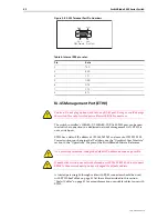
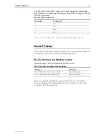
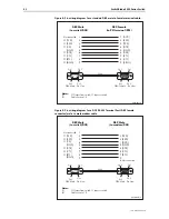
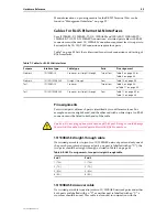
Page 41: ... use with the switch s RS 232 ASYN0 and RJ 45 interfaces RS 232 Terminal and Modem Cables Table 6 on page 41 list the cables described in this section Figure 4 on page 42 and Figure 5 on page 42 show how to wire cables to connect a standard VT100 compatible terminal or a modem to the switch controller s RS 232 Terminal Port Table 5 RJ 45 Pin assignments Pin Number Assignment1 1 TX 2 TX 3 RX 6 RX T...

Page 42: ...Pin 9 Pin 6 Pin 5 Pin 1 DB9 Female Pin View Pin 6 Pin 9 Pin 1 Pin 5 DB9 Male Pin View DB9 Male to switch DCE DB9 Female to PC terminal DTE Not connected TXD RXD CD GND DTR CTS RTS RING DCD RXD TXD DTR GND DSR RTS CTS RING Notes 1 Output from switch Input to switch 2 Cable version 1 0 DB9MDB9Fsw 3 TXD 2 RXD 1 DCD 5 GND 4 DTR 8 CTS 7 RTS 9 6 Not connected 1 2 3 4 5 6 7 8 9 Cable Pin 9 Pin 6 Pin 5 Pi...

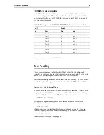
Page 43: ...bles with RJ 45 connectors 10 100BASE straight through cable If a twisted pair cable is to join two 10 100BASE network ports and only one of the ports has an internal crossover only one port is labelled with an X the two pairs should be straight through as listed in Table 8 on page 43 10 100BASE crossover cable If a twisted pair cable is used to join two 10 100BASE network ports and either both po...

Page 44: ...configuration This cable can also be used in conjunction with the software test facility to test 1000BASE network ports Table 10 on page 44 lists the pin assignments Table 9 RJ 45 Pin assignments two pair crossover cable End 1 End 2 1 TX 3 TX 2 TX 6 TX 3 RX 1 RX 6 RX 2 RX Table 10 Pin assignments 10 100 1000BASE T RJ 45 four pair straight through cable1 End 1 End 2 Pin Pair Pin Pair 1 Pair 1 1 Pai...

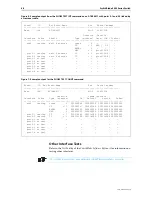
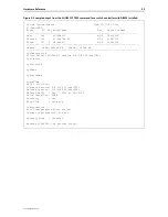
Page 45: ... can be thought of as a specialised interface module like PPP or Frame Relay Ethernet LAN Port Tests A crossover cable is required to run an Ethernet LAN test See Useful Cables on page 41 for details of how to make a suitable cable To start the test loop a crossover cable between any two RJ 45 line card ports and enter ENABLE TEST INT ALL All interfaces connected by crossover cables are tested Tes...

Page 46: ... minutes trans 0 TP 1 BAD 0 0 ENDEC 0 MAC 1 good 100 0 port3 1 testing wait 4 minutes TP 1 good 100 0 port3 2 testing wait 4 minutes TP 1 good 100 0 port3 3 no test port3 4 no test port3 5 no test port3 6 no test port3 7 no test port3 8 no test Board ID Bay Board Name Rev Serial number Base 164 AT SB4411 M1 0 50433214 Duration Frame Counters Interface State Type minutes Tx RxTotal RxGood RxBad eth...

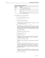
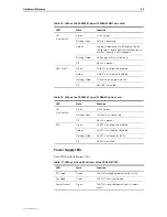
Page 47: ...r is receiving power Master Amber The switch controller is the master controller Off The switch controller is the slave controller Fault Red The switch controller or management software is malfunctioning 2 Flashes1 A fan tray fan has failed 3 Flashes1 A PSU or PSU fan is malfunctioning 5 flashes1 The fan tray has been removed for more than 20 seconds 6 Flashes1 The switch s internal temperature ha...

Page 48: ...RJ 45 Line Card LED State Function L A Default Green A 100 Mbps link is open Flashing green 100 Mbps activity is occurring Amber A 10 Mbps link is open The L A LEDs for ports 1 and 25 briefly light at switch power up or when the card is hot swapped in Flashing amber 10 Mbps activity is occurring D C LED Mode button pressed Green The port is operating at full duplex Amber The port is operating at h...

Page 49: ... enabled Amber A GBIC is installed but disabled Flashing Amber A fault is occurring on the link Off No GBIC is installed Table 16 LEDs on the AT SB4541 1 port 10GBASE LR Line Card LED State Function L A Link Activity Green A link is open Flashing Green 10GE activity is occurring Off No link is present XFP Green An XFP is installed and enabled Amber An XFP is installed but disabled Flashing Amber A...

Page 50: ...a cable The device at the other end of the connection is not working properly or is turned off The data cable is not wired correctly The network administrator has manually disabled the port through the software The port s selected transmission mode does not match that of the attached device Perform the following steps in sequence 1 Make sure the data cable connections are secure 2 Make sure the de...

Page 51: ...onnection you can still manage the switch via Telnet or SNMP until the problem is fixed 4 Remove the switch controller from the chassis and then re insert it 5 Download the latest software version See the SwitchBlade Software Reference for more information on how to obtain the latest software version Content Addressable Memory CAM CAM is an adaptation of random access memory RAM specifically desig...

Page 52: ...iptions shown in the Physical and Operating Specifications on page 15 for more information on the above line cards Expansion Options This section provides a brief overview of the expansion options for the SwitchBlade Contact your authorised Allied Telesis distributer or reseller for more information on these products or visit our Web site at www alliedtelesis com support software Dual In line Memo...

Page 53: ...t is provided on the front vent panel of the SwitchBlade chassis This socket is designed to be used in conjunction with an ESD wrist strap 3 To remove an existing DIMM Each DIMM is held in place by two retaining latches one latch at each end of the DIMM slot Release these latches and carefully pull the DIMM from the DIMM slot The location of DIMM slots is shown in Figure 8 on page 53 4 Align and i...

Page 54: ...s than the size of DIMM that has been installed then the switch has not correctly detected the DIMM The most likely cause is that the DIMM connector is not plugged into its slot correctly Repeat the installation process paying particular attention to the DIMM insertion step After repeating the installation use the SHOW SYSTEM command again and if the display is still not correct contact your autho...

Page 55: ...Blade 171 5 AT SB4411 M2 0 41362530 Memory DRAM 262144 kB FLASH 32768 kB SysDescription Allied Telesis AT SB4211 version 2 4 0 00 22 Aug 2001 SysContact SysLocation SysName SysDistName SysUpTime 8472 00 01 24 Software Version 2 4 0 00 22 Aug 2001 Release Version 2 4 0 00 22 Aug 2001 Release built Feb 7 2002 at 02 08 26 Patch Installed NONE Territory usa Help File help hlp Configuration Boot config...

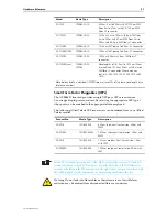
Page 56: ...ul link negotiation The following Allied Telesis GBIC transceivers can be ordered from your authorisedAllied Telesis reseller Small Form Factor Pluggables SFPs The AT SB4442 line card provides ports for 24 SFPs SFPs are miniature hot swappable plug in transceivers By selecting the appropriate SFP type 1 Gbps ports can be matched to the appropriate network interface RJ 45 copper or LC fibre The fol...

Page 57: ... SPSX 1000BASE SX 850nm 2m to 500m with 50 125µm MM fiber 2m to 275m with 62 5 125µm MM fiber LC connector AT SPLX10 1000BASE LX 1310nm 2m to 10km with 9µm SM fiber 2m to 550m with 50µm MM fiber 2m to 550m with 62 5µm MM fiber LC connector AT SPLX40 1000BASE LX 1310nm SM fiber up to 40km LC connector AT SPLX40 1550 1000BASE LX 1550nm SM fiber up to 40km LC connector AT SPZX80 1000BASE ZX 1550nm 80...

Page 58: ...ft Half duplex 412m 1360ft AT SB4411 Line Card 10BASE T 100BASE TX 1000BASE T RJ 45 CAT5 CAT5E 100 to 150m 328 to 492ft 200m 656ft AT SB4412 Line Card 10BASE T 100BASE TX 1000BASE T RJ 45 CAT5 CAT5E 100 to 150m 328 to 492ft 200m 656ft AT SB4441 Line Card 1000BASE X Varies with GBIC Refer to GBIC s user documentation Refer to GBIC s user documentation AT SB4451 Line Card 1000BASE SX SC 50 125 micro...

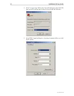
Page 59: ...enu The key to successful use of terminal emulation software with the switch is to configure the software and switch with matching communications parameters The following procedure can be applied to most terminal emulation programs Dialog boxes in the procedure are from Windows 2000 and XP Professional To configure Windows HyperTerminal for 2000 and XP Professional 1 Start the program in Windows b...

Page 60: ...60 00 REV H 3 In the Connect using field on the Connect To dialog box select the COM port on the PC used to connect to the switch and click the OK button 4 In the COMn Properties dialog box set port parameters as follows and click the OK button ...

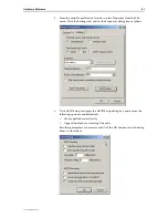
Page 61: ...ettings tab and set the Properties dialog box as follows 6 Click ASCII Setup to display the ASCII Setup dialog box and ensure the following options are not selected Echo typed characters locally Append line feeds to incoming line ends Set other parameters as necessary and click the OK buttons on both dialog boxes to close them ...

Page 62: ...nostics The switch software includes a set of diagnostic programs These programs perform basic level checks of all system components They do not run in conjunction with the normal operating code and require that the system be totally dedicated to their use A detailed knowledge of the way the switch hardware functions is necessary if diagnostics are to be used effectively The switch will not perfor...

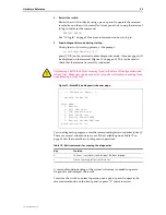
Page 63: ...ure you know how to reload these files before erasing flash or performing a flash test Figure 10 SwitchBlade diagnostics banner page To run a diagnostic program enter the corresponding letter or number or key There are several sub menus to cover all the available options Table 19 on page 63 lists the control keys for diagnostic operations A reasonable understanding of the system s structure is nee...

Page 64: ...vering all of the established markets in North America Latin America Europe Asia and the Pacific Allied Telesis provides localized sales and technical support worldwide To find our representative nearest you visit Allied Telesis on the web at http www alliedtelesis com support software ...

Reviews: