2262
PO
WER
S
UPPL
Y
RP
S
I
56V/18A M
AX
WARNING
This un
it may h
ave m
ore
electric
shock, d
isconne
unit.
100-240
VAC
~
16A
MAX
DC PW
R
FAULT
A
T
-PWR1200
226
3
PO
WER
S
UPPL
Y
RP
S
I
56V/18A
MAX
WARNING
This un
it may h
ave more
electric
shock, discon
ne
unit.
100-240
VAC
~
5A MAX
DC PWR
FAULT
A
T
-PWR250
x610 Series Layer 3 Gigabit Ethernet Switches Installation Guide
85
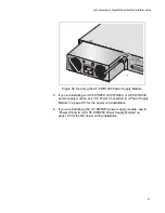
Figure 51. Installing the AT-PWR1200 Power Supply Module
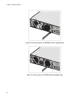
4. Secure the power supply module to the chassis by tightening the two
captive screws with a cross-head screwdriver, as shown in Figure 61
and Figure 62.
Figure 52. Securing the AT-PWR250 Power Supply Module


