Chapter 4: Beginning the Installation
108
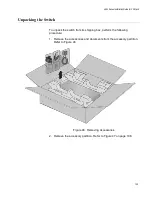
5. Visually inspect the product for damage.
6. Visually inspect the front panel for the components shown in Figure 1
7. Verify that there are two pre-installed fan modules in FAN A and FAN
B slots on the rear panel. Refer to Figure 2 on page 21 and “FAN05
Note
Do not power on the switch if it is missing a fan module.
Summary of Contents for x950 Series
Page 12: ...Figures 12 ...
Page 18: ...Preface 18 ...
Page 50: ...Chapter 1 Overview 50 ...
Page 70: ...Chapter 2 XEM2 Ethernet Line Cards 70 ...
Page 134: ...Chapter 5 Installing Power Supplies and Optional XEM2 Line Card 134 ...
Page 146: ...Chapter 7 Installing the Switch in an Equipment Rack 146 ...
Page 162: ...Chapter 8 Installing the Switch on a Wall 162 ...
Page 224: ...Chapter 12 Powering On and Verifying the Stack 224 ...
Page 256: ...Chapter 14 Replacing Modules 256 ...


