x950 Series Installation Guide for VCStack
137
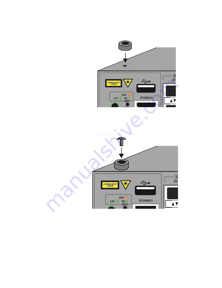
3. Place the bumper foot onto one of the holes in the base of the switch.
Refer to Figure 80.
Figure 80. Placing the Bumper Foot on a Base Corner Hole
4. Insert the rivet to secure the bumper foot to the base. Refer to
Figure 81. Inserting the Rivet into the Bumper Foot
5. Repeat steps 2 to 4 to install the remaining bumper feet.
6. Turn the switch over and place it on a flat, secure desk or table, leaving
ample space around it for ventilation.
Summary of Contents for x950 Series
Page 12: ...Figures 12 ...
Page 18: ...Preface 18 ...
Page 50: ...Chapter 1 Overview 50 ...
Page 70: ...Chapter 2 XEM2 Ethernet Line Cards 70 ...
Page 134: ...Chapter 5 Installing Power Supplies and Optional XEM2 Line Card 134 ...
Page 146: ...Chapter 7 Installing the Switch in an Equipment Rack 146 ...
Page 162: ...Chapter 8 Installing the Switch on a Wall 162 ...
Page 224: ...Chapter 12 Powering On and Verifying the Stack 224 ...
Page 256: ...Chapter 14 Replacing Modules 256 ...

