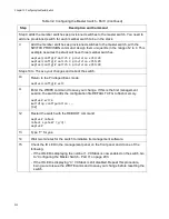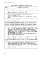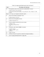
Chapter 10: Configuring the Master Switch
190
STACK
PRIORITY
This command is used to assign priority numbers to switches.Switches
use the numbers to select the master switch. The lower the number the
higher the priority. The unit with the lowest number becomes the master. If
they have the same priority value, they use their MAC addresses to
determine the master. As with priority numbers, the lower the MAC
address, the higher the priority. A switch can have only one priority
number.
Allied Telesis recommends making a switch’s priority and ID numbers the
same. This is not required, but it can make managing and troubleshooting
a stack easier.
The format of the command, which is in the Global Configuration mode, is
shown here:
stack
switch_ID
priority
priority_number
The variables are defined here:
switch_ID - This is the ID number of the switch. The range is 1 to 8.
You can specify only one ID number.
priority_number - This is the new priority number for the switch.
You can specify only one number. The range is 0 to 255. The
default is 128.
This example assigns the priority 1 to the switch with ID 1:
awplus(config)# stack 1 priority 1
STACK
RENUMBER
Every switch in a stack has to have a unique ID number assigned with this
command. Here is the format.
stack
current_switch_ID
renumber
new_switch_ID
The variables are defined here:
current_switch_ID - This is the current ID number of the switch.
You can specify only one ID number.
new_switch_ID - This is the new ID number for the switch. You can
specify only one number. The range is 1 to 8. The default is 1.
Changing the ID number requires resetting the switch.
This example changes the switch’s ID from the default 1 to 2:
awplus(config)# stack 1 renumber 2
SWITCH
PROVISION
To ensure that the first power-on of the stack is successful, Allied Telesis
recommends configuring the units such that each unit knows about the
others prior to forming the stack. This involves using the SWITCH
Summary of Contents for x950 Series
Page 12: ...Figures 12 ...
Page 18: ...Preface 18 ...
Page 50: ...Chapter 1 Overview 50 ...
Page 70: ...Chapter 2 XEM2 Ethernet Line Cards 70 ...
Page 134: ...Chapter 5 Installing Power Supplies and Optional XEM2 Line Card 134 ...
Page 146: ...Chapter 7 Installing the Switch in an Equipment Rack 146 ...
Page 162: ...Chapter 8 Installing the Switch on a Wall 162 ...
Page 224: ...Chapter 12 Powering On and Verifying the Stack 224 ...
Page 256: ...Chapter 14 Replacing Modules 256 ...


