x950 Series Installation Guide for VCStack
251
Replacing FAN05 Modules
This section contains the procedure for replacing FAN05 Modules. Fan
modules are hot swappable. You can replace them without having to
power off the switch. For background information, refer to “FAN05 Cooling
Note
Allied Telesis recommends saving a backup copy of the
configuration file in the switch before replacing a fan module. For
instructions, refer to the Software Reference for x950 Switches
.
Removing Fan
Modules
This procedure requires the following tool:
#2 Phillips-head screwdriver (not provided)
The illustrations show the removal of the fan module from FAN B slot on
the back panel. The procedure is the same for removing a module from
FAN A slot.
To remove a fan module from the switch, perform the following procedure:
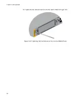
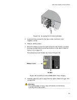
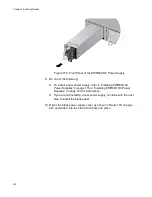
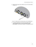
1. Use a #2 Phillips-head screwdriver to loosen the two screws on the
faceplate of the fan module. Refer to Figure 151.
Figure 151. Loosening the Screws on the Fan Module
Summary of Contents for x950 Series
Page 12: ...Figures 12 ...
Page 18: ...Preface 18 ...
Page 50: ...Chapter 1 Overview 50 ...
Page 70: ...Chapter 2 XEM2 Ethernet Line Cards 70 ...
Page 134: ...Chapter 5 Installing Power Supplies and Optional XEM2 Line Card 134 ...
Page 146: ...Chapter 7 Installing the Switch in an Equipment Rack 146 ...
Page 162: ...Chapter 8 Installing the Switch on a Wall 162 ...
Page 224: ...Chapter 12 Powering On and Verifying the Stack 224 ...
Page 256: ...Chapter 14 Replacing Modules 256 ...


