207
Alvium USB Cameras User Guide V3.6.4
Triggering
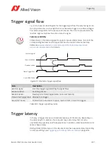
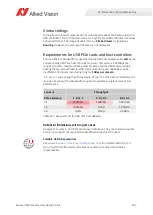
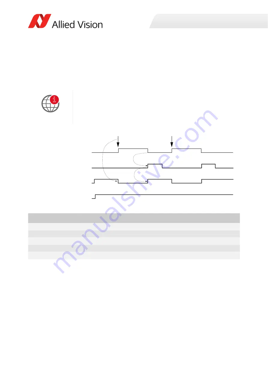
Trigger signal flow
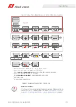
Figure 85
shows an ideal diagram for the trigger signal flow. The external signal can
be a physical source, such as light barrier as hardware trigger or a software trigger.
This external signal starts the exposure of a frame. The end of exposure starts the
readout. High levels show the active state of a signal.
Trigger latency
In theory, a trigger creates an immediate response of the camera, depending on
the cable length. In practice, the computer may add a delay that is mostly
unpredictable, especially on Windows systems. In addition, camera electronics and
sensors have a delay.
Rolling shutter (RS) cameras in this document also have exposure delay, depending
on camera settings, see
Triggering with rolling shutter cameras
Features availability
States shown in the following graphic apply to Alvium USB cameras. Not all of the
corresponding features may be supported. See the Alvium Cameras Features
Reference at
www.alliedvision.com/en/support/technical-documentation/
for details.
Figure 85: Schematic trigger signal flow
Term
Description
External signal
Electrical trigger signal starting the signal flow
Exposure Active
Exposing a frame
Readout Active
Reading out a frame (logical state, not a user feature)
Frame Start Trigger Wait Waiting for a trigger
Acquisition Active
Enables frame acquisition: Expose, read out data, or wait for triggers.
Table 105: Trigger signal flow terms
i
External signal
džƉŽƐƵƌĞĐƟǀĞ
ZĞĂĚŽƵƚĐƟǀĞ
FrameTriggerWait
ĐƋƵŝƐŝƟŽŶĐƟǀĞ
Frame 1
1
2
Frame 2
Frame 2
Frame 1

