Preparing Cameras without
Sensor Cover Glass
Page 11 of 18
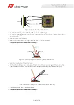
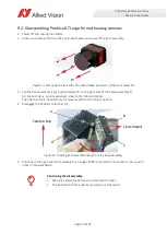
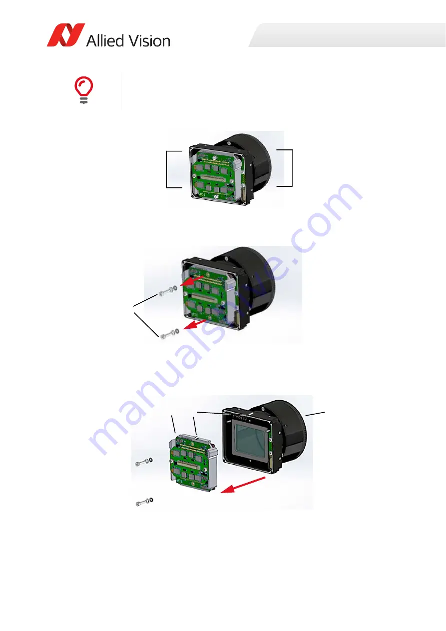
The front assembly consists of the sensor unit (e) and the lens mount (f).
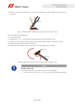
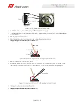
6. Remove the two M2 x 10 socket head cap screws (g) and spacers from the sensor unit.
7. With a water resistant ink pen, draw a line (i) across the center top of sensor unit and front assembly.
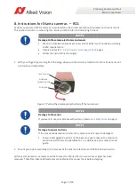
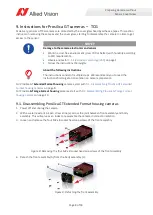
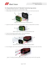
8. Remove the sensor unit (h) from the lens mount (k).
Continuing the disassembly
• Keep the camera flipped open as described in step
• The illustrations of the next action steps are schematics.
Figure 15: Front assembly overview: sensor unit and lens mount
Figure 16: Loosening the two M2 x 10 socket head cap screws and spacers
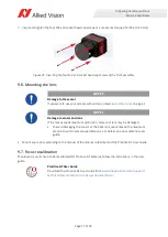
Figure 17: Removing the sensor unit from the lens mount
e
f
g
h
k
i

