Camera interfaces
188
Prosilica GT Technical Manual V3.2.0
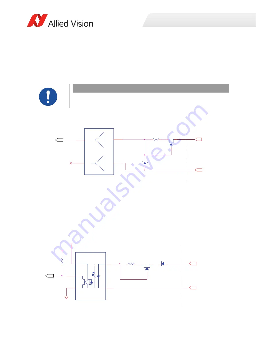
In 1 (Non-isolated)
In 1
is not electrically isolated and can be used when environmental noise is
insignificant and faster trigger response is required. The required trigger signal is
low voltage TTL 3.3 volts. Tie trigger ground to Camera GND to complete the
trigger circuit.
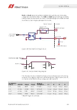
In 2 (Opto-isolated)
In 2
is optically isolated and can be used in electrically noisy environments to
prevent false trigger events. Tie trigger ground to Isolated IO GND to complete the
trigger circuit. Compared to the non-isolated trigger,
In 2
has a longer propagation
time. It can be driven from 5 to 24 volts with a minimum current source of 5 mA.
NOTICE
Power caution
Exceeding 5.1 volts on
In 1
can permanently damage the camera.
Figure 117: Internal circuit diagram for non-isolated input trigger
Figure 118: Internal circuit diagram for opto-isolated input trigger
To Camera Logic
Camera GND
1Y
SN
7
4L
V
C2G34DCKR
2
3
6
4
In 1
D
S
G
180 R
1/10
W
2Y
1
A
2
A
Camera Internal
E
x
ternal
5.1
V
, 150 m
W
To Camera Logic
Isolated IN GND
PS911
7A
-F3-
A
X
1
2
4
3
5
3.3
V
In 2
D
S
G
180 R
1/10
W
Camera Internal
E
x
ternal
4.
7
5 K
50
V
, 1
A
3.3
V


