Guppy PRO Technical Manual
V4.1.2
68
11
---
---
---
---
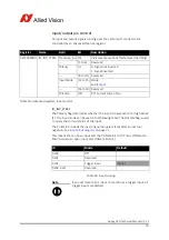
White/Black
12
Camera Out 2 Out
Open emitter
Camera Output 2
(GPOut2)
default: Off
White/Brown
Note
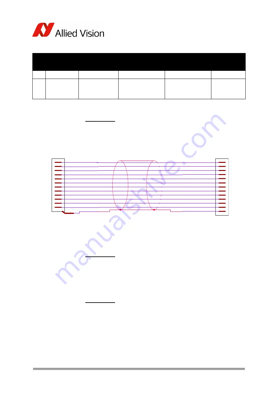
For cable color and pin out information, see the
Allied Vision
I/O cable data sheet
:
https://www.alliedvision.com/en/support/technical-
documentation/accessories-data-sheets.html
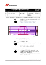
Figure 26: Guppy PRO cable color coding
Note
12-pin Hirose I/O cables
The General Purpose I/O port has a Hirose HR10-10R-12PA(73)
connector on the camera side. The mating cable connector is:
• Hirose HR10A-10P-12S(73) for soldering
• Hirose HR10A-10P-12SC(73) for crimping
Note
GP = General Purpose
For a detailed description of the I/O connector and its
operating instructions see the
1394 Installation Manual
,
Chapter
Guppy PRO input description
.
Read all Notes and Cautions in the
1394 Installation Manual
,
before using the I/O connector.
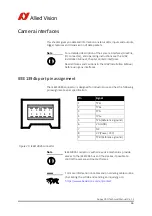
Camera side Hirose HR10-10R-12PA(73) connector
Trigger cable
color code
Pin
Signal
Direction
Level
Description
Table 20: Camera I/O connector pin assignment and Guppy PRO trigger cable color coding (continued)
Hirose HR10A
.
.
.
.
.
.
.
.
.
.
.
.
SHIELD
1
2
3
4
5
6
7
8
9
10
11
12
.
BLUE
RED
PINK
GREY
YELLOW
GREEN
BROWN
WHITE
BLACK
ORANGE
WHITE/BLACK
WHITE/BROWN
Open End
.
.
.
.
.
.
.
.
.
.
.
.
TRANSPARENT
.
.
.
.
.
.
.
.
.
.
.
.
.

