Camera interfaces
82
Mako G Technical Manual V4.2.2
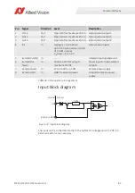
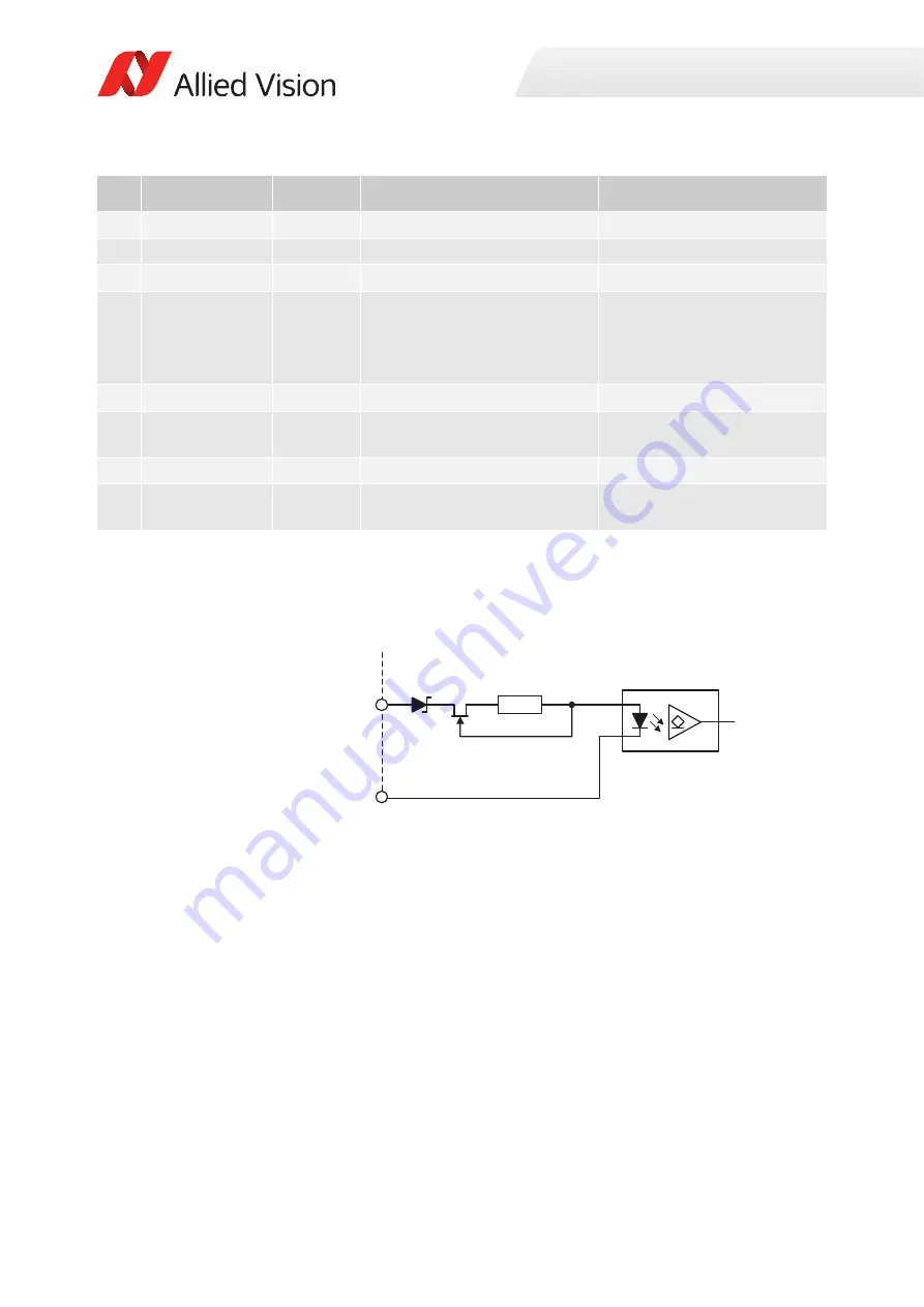
Input block diagram
The input can be connected directly to the system for voltages up to 24 VDC. An
external resistor is not necessary.
Pin
Signal
Direction
Level
Description
1
Out 1
Out
Open emitter, maximum 20 mA
Opto-isolated output 1
2
Out 2
Out
Open emitter, maximum 20 mA
Opto-isolated output 2
3
Out 3
Out
Open emitter, maximum 20 mA
Opto-isolated output 3
4
In 1
In
U
in
(high) = 3.0 to 24.0 V
up to 36 V with external resistor
of 3.3 k
in series
U
in
(low) = 0 to 1.0 V
Opto-isolated input 1
5
Isolated In GND
In
---
Isolated input signal ground
6
Isolated Out
Power
In
Common VCC for outputs
maximum 30 VDC
Power input for opto-isolated
outputs
7
Camera Power
In
12 to 24 VDC +/- 10%
Camera power supply
8
Camera GND
In
GND for external power
Ground for camera power
supply
Table 38: I/O connector pin assignment
Figure 37: Input block diagram
In1
Isolated In GND
External Internal
180R


