Camera interfaces
77
Mako U Technical Manual V1.1.3
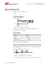
Output description
Figure 29: Opto-isolated output, block diagram
Physical and logical lines
A logical
high in Vimba
is a
physical low level
due to the open collector output
circuit.
Inverting the logical signal level
To ease camera control, you can invert the logical signal level with the
LineInverter
feature. See
USB Features Reference
at
Additional Documents
for the Mako U camera:
https://www.alliedvision.com/en/support/technical-documentation
.
Logical signal
Vimba value
Voltage level
Active
High
Low
No signal
Low
High
Table 30: Opto-isolated output, physical and logical lines
External supply voltage
Internal
External
Isolated GND
Pin 5
Out 1
Pin 4
R
ext
i


