Camera interfaces
81
Mako U Technical Manual V1.1.3
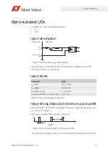
Input levels
The GPIOs can be connected directly to the system for voltages up to 24 VDC.
An external resistor is not necessary.
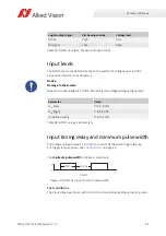
Input timing delay and minimum pulse width
The hardware input delay is 10 to 70 ns, it is part of the entire trigger latency.
For trigger latency values, see
The
minimum pulse width
for Mako U cameras is:
Test conditions
The input signal was driven with 3.3 VDC and no external additional serial resistor.
Logical output signal
Vimba output value
Voltage level
Active
High
Low
No signal
Low
High
Table 35: GPIOs as output, physical and logical lines
Notice
Damage to the camera
Maximum input voltage is 30 VDC. Exceeding this voltage damages the camera.
Parameter
Value
U
in
(low)
0 to 0.8 VDC
U
in
(high)
2 to 24 VDC
Undefined levels
0.8 to 2 VDC
Table 36: GPIOs as input, parameters
Figure 32: GPIOs as input, minimum pulse width
I
F
0
t
100 ns
5 MHz
100 ns


