Appendix
126
Prosilica GC Technical Manual V2.2.0
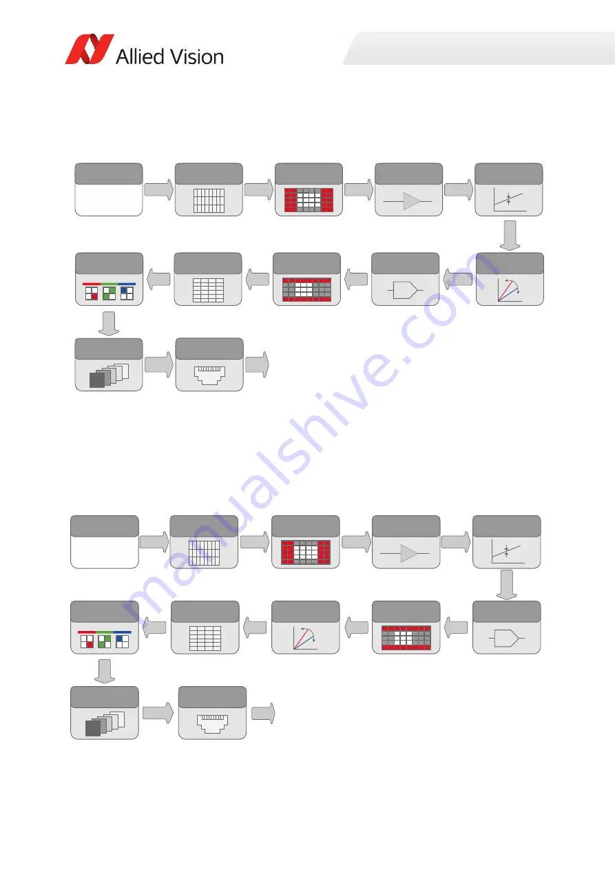
Prosilica GC color cameras
Prosilica GC750C
Figure 64: Image data flow diagram of color Prosilica GC cameras (except GC750C)
Figure 65: Image data flow diagram for Prosilica GC750C
Sensor
Gain
Offset
2
ADC
Horizontal
ROI
Horizontal
Binning
3
Bayer
Interpolation
Analog
12
bit
Analog
Analog
Analog
Analog
12
bit
12
bit
8
bit
8/12
bit
White
balance
GigE
Interface
Frame
Memory
1
Color
information
lost
while
vertical
binning
is
active.
2
Factory
calibrated.
Not
a
user
control.
3
For
on
Ͳ
camera
interpolated
PixelFormats
only
(8
Ͳ
bit
output).
Raw
un
Ͳ
interpolated
PixelFormats
skip
this
block
(8/12
bit
output
depending
upon
the
bit
depth
of
PixelFormat
used).
Vertical
ROI
Analog
GigE
Vertical
Binning
1
Sensor
Gain
Offset
2
Vertical
ROI
Vertical
Binning
1
Bayer
Interpolation
3
Horizontal
Binning
White
balance
Horizontal
ROI
ADC
Frame
Memory
GigE
Interface
8/10
bit
Analog
Analog
Analog
Analog
Analog
10
bit
10
bit
10
bit
8
bit
10
bit
GigE
1
Color
information
lost
while
vertical
binning
is
active.
2
Factory
calibrated.
Not
a
user
control.
3
For
on
Ͳ
camera
interpolated
PixelFormats
only
(8
Ͳ
bit
output).
Raw
un
Ͳ
interpolated
PixelFormats
skip
this
block
(10
Ͳ
bit
output).

