Specifications
24
Prosilica GC Technical Manual V2.2.0
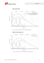
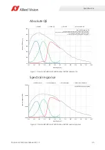
Absolute quantum efficiency plots
Spectral response plots
Important notice before reading the quantum efficiency plots
All measurements were done without protection glass or IR cut filter. With
protection glass or filters, quantum efficiency (QE) decreases by approximately
10%.
The uncertainty in measurement of the QE values is
10%.
This is due to:
•
Manufacturing tolerance of the sensor
•
Uncertainties in the measuring apparatus itself (Ulbricht sphere, optometer,
etc.)
Absolute QE plots for Sony CCD/CMOS sensors
Sony provides relative response curves in their sensor data sheets. To create the
absolute QE plots shown in this chapter, the relative response was converted to a
normalized QE response and then adjusted as per three measured QE values (@
448 nm, 529 nm, 632 nm) for color sensors and one measured QE value (@ 529
nm) for monochrome sensors.
Absolute QE plots for OnSemi CCD sensors
The curves in the absolute QE plots shown in this chapter are from the sensor
manufacturer data sheet.
The information was correct at the time of publishing. Sensor specifications may
change without notice.
Wavelength
The wavelength range in the absolute QE plots is based on the information
available in the sensor manufacturer data sheet at the time of publishing. Many
color sensors are documented by the sensor manufacturer only for wavelengths
from 400 nm to 700 nm.
For additional wavelength information, please contact the sensor manufacturer.
Sony provides relative response curves in their sensor data sheets. To create the
spectral response plots shown in this chapter, the relative response was adjusted
as per three measured QE values (@ 448 nm, 529 nm, 632 nm) for color sensors
and one measured QE value (@ 529 nm) for monochrome sensors.


