Camera interfaces
61
Prosilica GC Technical Manual V2.2.0
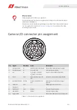
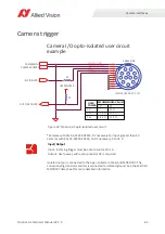
The general purpose I/O port uses a Hirose HR10A-10R-12PB connector on the
camera side. The mating cable connector is Hirose HR10A-10P-12S.
I/O definition
Camera power
The Prosilica GC camera family has recently been updated to offer an expanded
input power voltage range. The camera serial number is used to differentiate
between cameras that offer 5 to 16 VDC and those that offer 5 to 25 VDC.
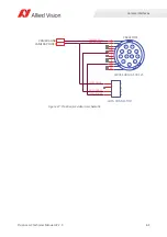
Isolated IO ground
The Isolated IO GND connection provides the user ground reference and return
path for In 1, and Out 1. It is recommended that the ground wiring be physically
close to the In/Out wiring to prevent parasitic coupling. For example, a good cable
design connects In 1 to one conductor of a twisted pair, Isolated IO GND to the
second conductor of the same twisted pair.
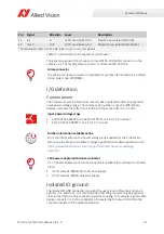
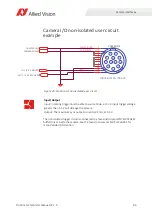
11
In 2
In
LVTTL maximum 3.3 V
Input 2 non-isolated (SyncIn2)
12
Out 2
Out
LVTTL maximum 3.3 V
Output 2 non-isolated (SyncOut2)
*Some models offer 5 to 25 VDC. See
for details.
Hirose connector
The cable side Hirose connector is available for purchase from Allied Vision (Allied
Vision order code K7600040).
Input power voltage range
•
SN 02-XXXXX-06000 to 02-XXXXX-07999: 5 to 16 V. 12 V nominal.
•
SN
≥
02-XXXXX-08XXX: 5 to 25 V. 12 V nominal
Further information available online
For more information on the power voltage range update for the Prosilica GC
family, see the Prosilica GC Power Voltage Specification Update application note:
https://www.alliedvision.com/en/support/technical-papers-knowledge-
base.html
12V power adapter with Hirose connector
A 12 V power adapter with Hirose connector is available for purchase from Allied
Vision:
•
Order code 02-8003D North America Supply.
•
Order code 02-8004D Universal Supply.
Pin
Signal
Direction
Level
Description
Table 17: I/O connector pin assignment (continued)
i

