507335-01
Page 34 of 44
Issue 1624
Heat Pump
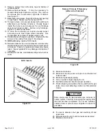
For heat pump operation, clip the jumper wire located below
the O terminal on the integrated ignition/blower control board.
In heat pump mode, a call for heat will result in the circulating
air blower operating at the selected cooling airflow after a
brief ramp-up period.
Emergency Replacement Motor Operation
If the variable speed motor needs to be replaced in an
emergency situation (such as “no heat”) and an exact
replacement motor is not immediately available, a standard
PSC motor of equivalent frame size, voltage, rotation, and
horsepower can be
temporarily
installed until the correct
replacement motor can be obtained.
Connect the desired speed tap to the “EAC” terminal and
the neutral tap to the neutral terminal on the ignition control
(refer to the furnace wiring diagram). The ignition control will
control the motor’s operation, including a nominal 20 second
“on” delay with a call for heat and a nominal 180 second “off”
delay when the thermostat is satisfied. It will also operate
the motor on a call for cooling, with no “on” or “off” delays.
Verify that the unit is operating at the desired speed and
within the rise range as shown on the unit rating plate.
The correct replacement motor must be installed as
soon as possible to ensure continued satisfactory
operation of the furnace.
IMPORTANT
The system must not be in either the passive or active
dehumidification mode when charging a cooling system.
Fan On
When the thermostat is set for continuous fan operation
and there is no demand for heating or cooling, a call for
fan closes
the R to G circuit and the circulating blower motor runs at
50% of the selected cooling CFM until switched off. When
the call for fan is turned off, the control de-energizes the
circulating blower.
Cooling
The unit is set up at the factory for single stage cooling. For
two stage cooling operation, clip the jumper wire located
between the Y to Y2 terminals on the integrated ignition/
blower control board.
If the active dehumidification feature is enabled, the
circulating blower runs at 82% of the selected cooling speed
as long as there is a call for dehumidification.
Single Stage Cooling
A call for cooling from the thermostat closes the R to Y circuit
on the integrated ignition/blower control board. The control
waits for a 1-second delay before energizing the circulating
blower to 82% of the selected cooling CFM (passive
dehumidification mode). After 7.5 minutes, the circulating
blower automatically ramps up to 100% of the selected
cooling airflow. When the call for cooling is satisfied, the
circulating blower ramps back down to 82% of the selected
cooling airflow for 1 minute, then shuts off.
Two Stage Cooling
A call for 1
st
stage cooling from the thermostat closes the
R to Y circuit on the control board. The control waits for
a 1-second delay before energizing the circulating blower.
The blower motor runs at 57% of the selected air flow for the
first 7.5 minutes of the 1
st
stage cooling demand (passive
dehumidification mode). After 7.5 minutes, the blower motor
runs at 70% of the selected cooling air flow until 1
st
stage
cooling demand is satisfied.
A call for 2
nd
stage cooling from the thermostat closes the
R to Y2 circuit on the control board. The blower motor
ramps up to 100% of the selected cooling air flow. When
the demand for cooling is met, the blower ramps down to
Y1 until satisfied, then ramps down to 57% for 1 minute,
then turns off.
Summary of Contents for 80G2UH-V
Page 29: ...507335 01 Page 29 of 44 Issue 1624 ADJUSTING AIRFLOW Table 11 ...
Page 41: ...507335 01 Page 41 of 44 Issue 1624 Wiring Diagram Figure 41 ...
Page 42: ...507335 01 Page 42 of 44 Issue 1624 Typical Field Wiring Diagram Figure 42 ...
Page 43: ...507335 01 Page 43 of 44 Issue 1624 Start Up Performance Check List UNIT SET UP ...
Page 44: ...507335 01 Page 44 of 44 Issue 1624 UNIT OPERATION ...

