507335-01
Page 8 of 44
Issue 1624
When ducts are used, they shall be of the same cross
sectional area as the free area of the openings to which they
connect. The minimum dimension of rectangular air ducts
shall be no less than 3 inches (75 mm). In calculating free
area, the blocking effect of louvers, grilles, or screens must
be considered. If the design and free area of protective
covering is not known for calculating the size opening
required, it may be assumed that wood louvers will have
20 to 25 percent free area and metal louvers and grilles
will have 60 to 75 percent free area. Louvers and grilles
must be fixed in the open position or interlocked with the
equipment so that they are opened automatically during
equipment operation.
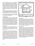
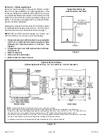
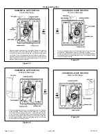
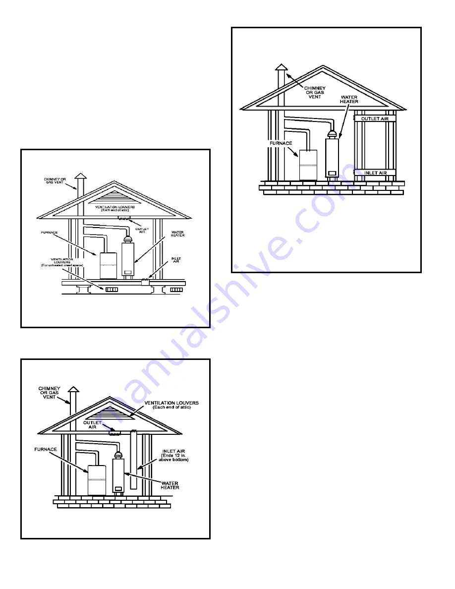
EQUIPMENT IN CONFINED SPACE
(ALL AIR FROM OUTSIDE)
NOTE:
Each air duct opening shall have a free area of at least one
square inch per 2,000 Btu (645 mm² per .59 kW) per hour of the total
input rating of all equipment in the enclosure. If the equipment room
is located against an outside wall and the air openings communicate
directly with the outdoors, each opening shall have a free area of at
least 1 square inch per 4,000 Btu (645 mm² per 1.17 kW) per hour of
the total input rating of all other equipment in the enclosure.
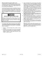
Figure 6
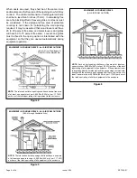
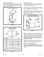
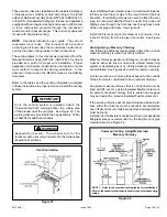
EQUIPMENT IN CONFINED SPACE - ALL AIR FROM OUTSIDE
(All Air through Ventilated Attic)
NOTE:
The inlet and outlet air openings shall each have a free area
of at least one square inch per 4,000 Btu (645 mm² per 1.17 kW)
per hour of the total input rating of all equipment in the enclosure.
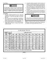
Figure 5
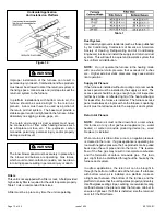
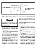
Figure 4
EQUIPMENT IN CONFINED SPACE - ALL AIR FROM OUTSIDE
NOTE:
The inlet and outlet air openings shall each have a free area
of at least one square inch per 4,000 Btu (645 mm² per 1.17 kW)
per hour of the total input rating of all equipment in the enclosure.
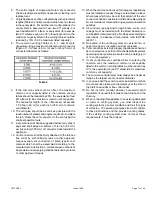
(Inlet Air from Crawlspace &
Outlet Air to Ventilated Attic)
Summary of Contents for 80G2UH-V
Page 29: ...507335 01 Page 29 of 44 Issue 1624 ADJUSTING AIRFLOW Table 11 ...
Page 41: ...507335 01 Page 41 of 44 Issue 1624 Wiring Diagram Figure 41 ...
Page 42: ...507335 01 Page 42 of 44 Issue 1624 Typical Field Wiring Diagram Figure 42 ...
Page 43: ...507335 01 Page 43 of 44 Issue 1624 Start Up Performance Check List UNIT SET UP ...
Page 44: ...507335 01 Page 44 of 44 Issue 1624 UNIT OPERATION ...


