background image

507335-01

Page 43 of  44

Issue 1624

Start-Up & Performance Check List

UNIT SET UP

Summary of Contents for 80G2UH-V

Page 1: ... or loss of life Installation and service must be performed by a licensed professional installer or equivalent service agency or the gas supplier WARNING As with any mechanical equipment personal injury can result from contact with sharp sheet metal edges Be careful when you handle this equipment CAUTION Table of Contents Unit Dimensions 2 Parts Arrangement 3 A80UH2V 80G2UH V Gas Furnace 4 Shippin...

Page 2: ...35 x 25 mm cleanable air filter Required to maintain proper air velocity 2 Single side return air with optional RAB Return Air Base 3 Return Air from bottom and one side 4 Return air from both sides 5 Return air from bottom 2 Flue outlet may be horizontal but furnace must be vented vertically 3 Optional external side return air filter kit cannot be used with the optional RAB Return Air Base Consid...

Page 3: ...OL BOX BLOWER ASSEMBLY BURNER ACCESS PANEL BURNER BOX GAS VALVE COMBUSTION AIR INDUCER PRESSURE SWITCH COMBUSTION AIR INDUCER HEAT EXCHANGER CABINET Figure 1 BLOWER ACCESS PANEL INCLUDES INTEGRATED CONTROL AND TRANSFORMER ROLLOUT LOCATED INSIDE BURNER BOX ...

Page 4: ... the absence of local codes units must be installed according to the current National Fuel Gas Code ANSI Z223 1 The National Fuel Gas Code is available from the following address American National Standards Institute Inc 11 West 42nd Street New York NY 10036 Clearances Adequate clearance must be made around the air openings into the vestibule area In order to ensure proper unit operation combustio...

Page 5: ...rmostat must control the furnace The use of fixed jumpers that will provide continuous heating is not allowed The return air duct must be provided and sealed to the furnace Return air temperature range between 60 F 16 C and 80 F 27 C must be maintained Air filters must be installed in the system and must be maintained during construction Air filters must be replaced upon construction completion Th...

Page 6: ... chimney As a result combustion gases enter the living space creating a potentially dangerous situation In the absence of local codes concerning air for combustion and ventilation use the guidelines and procedures in this section to install these furnaces to ensure efficient and safe operation You must consider combustion air needs and requirements for exhaust vents and gas piping A portion of thi...

Page 7: ...taining the furnace the return air must be handled by ducts which are sealed to the furnace casing and which terminate outside the space containing the furnace This is especially important when the furnace is mounted on a platform in a confined space such as a closet or small equipment room Even a small leak around the base of the unit at the platform or at the return air duct connection can cause...

Page 8: ... area of at least one square inch per 2 000 Btu 645 mm per 59 kW per hour of the total input rating of all equipment in the enclosure If the equipment room is located against an outside wall and the air openings communicate directly with the outdoors each opening shall have a free area of at least 1 square inch per 4 000 Btu 645 mm per 1 17 kW per hour of the total input rating of all other equipm...

Page 9: ...washer have been removed the rigid leg will not touch the blower housing Setting Equipment WARNING Do not install the furnace on its front or its back Do not connect the return air ducts to the back of the furnace Doing so will adversely affect the operation of the safety control devices which could result in personal injury or death Upflow Applications Allow for clearances to combustible material...

Page 10: ...er air velocity See Figure 9 2 Single side return air with optional return airbase See Figure 10 3 Bottom return air 4 Return air from both sides 5 Bottom and one side return air Figure 9 Single Side Return Air with transition and filter Optional Return Air Base Upflow Applications Only For use with A B C and D cabinets NOTE Optional Side Return Air Filter Kits are not for use with Return Air Base...

Page 11: ...r ceiling joists When straps are used to suspend the unit in this way support must be provided for both the ends The straps must not interfere with the plenum or exhaust piping installation Cooling coils and supply and return air plenums must be supported separately NOTE When the furnace is installed on a platform in a crawlspace it must be elevated enough to avoid water damage and to allow the ev...

Page 12: ...own the vent pipe and into the room This reverse flow of the flue gas may result in incomplete combustion and the formation of carbon monoxide gas This toxic gas might then be distributed throughout the house by the furnace duct system In upflow applications the return air can be brought in through the bottom or either side of the furnace If a furnace with bottom return air is installed on a platf...

Page 13: ...ressure switch assembly to the orifice plate Lift the assembly and rotate it 90 clockwise or counter clockwise to either the 3 o clock position or 9 o clock position Resecure with four secrews Gasket should be left in place 2 Use tin snips to cut preferred opening on the cabinet for repositioning the flue outlet Use the cut out piece as a cover plate to patch unused opening on cabinet Figure 17 Re...

Page 14: ...ssembly 2 screws and cut wire tie to free make up box wires Reinstall make up box on other side of cabinet Resecure make up box wires Either pull excess wires through the blower compartment and secure using supplied wire tie or coil excess wire and secure to the gas manifold HORIZONTAL RIGHT POSITION Side Vent Discharge Figure 22 HORIZONTAL LEFT POSITION Side Vent Discharge Figure 20 Disconnect pr...

Page 15: ...ING Use self drilling sheet metal screws or a mechanical fastener to firmly secure the vent pipe to the round collar of the flue transition If self drilling screws are used to attach the vent pipe it is recommended that three be used Drive one self drilling screw through the front and one through each side of the vent pipe and collar See Figure 23 Install the first vent connector elbow at a minimu...

Page 16: ...ney Never connect a Category I appliance to a chimney that is servicing a solid fuel appliance If a fireplace chimney flue is used to vent this appliance the fireplace opening must be permanently sealed Atype B or listed chimney lining system that passes through an unused masonry chimney flue is not considered to be exposed to the outdoors General Venting Requirements Vent these furnaces according...

Page 17: ...ints between sections of single wall connector piping shall be fastened by screws or other approved means 13 When the vent connector used for Category I appliances must be located in or pass through a crawl space attic or other areas which may be cold that portion of the vent connector shall be constructed of listed doublewall type B vent material or material having equivalent insulation qualities...

Page 18: ... configurations with zero lateral lengths are assumed to have no elbows in the vent system For all other vent configurations the vent system is assumed to have two 90 elbows For each additional 90 elbow or equivalent for example two 45 elbows equal one 90 elbow beyond two the maximum capacity listed in the venting table should be reduced by 10 percent 0 90 x maximum listed capacity ...

Page 19: ...configurations with zero lateral lengths are assumed to have no elbows in the vent system For all other vent configurations the vent system is assumed to have two 90 elbows For each additional 90 elbow or equivalent for example two 45 elbows equal one 90 elbow beyond two the maximum capacity listed in the venting table should be reduced by 10 percent 0 90 x maximum listed capacity ...

Page 20: ... Capacity Type B Double Wall Vents with Type B Double Wall Connectors Serving Two or More Category I Appliances Common Vent Capacity Type B Double Wall Vents with Type B Double Wall Connectors Serving Two or More Category I Appliances Table 5 Table 6 ...

Page 21: ... Two or more Category I Appliances Table 8 NOTE Single appliance venting configurations with zero lateral lengths are assumed to have no elbows in the vent system For all other vent configurations the vent system is assumed to have two 90 elbows For each additional 90 elbow or equivalent for example two 45 elbows equal one 90 elbow beyond two the maximum capacity listed in the venting table should...

Page 22: ...m are located and other spaces of the building Turn on clothes dryers and any appliances not connected to the common venting system Turn on any exhaust fans such as range hoods and bathroom exhausts so they will operate at maximum speed Do not operate a summer exhaust fan Close fireplace dampers 4 Follow the lighting instructions Turn on the appliance that is being inspected Adjust the thermostat ...

Page 23: ...e The piping must be supported at proper intervals every 8 to 10 feet 2 44 to 3 01 m with suitable hangers or straps Install a drip leg in vertical pipe runs to the unit 5 A 1 8 N P T plugged tap or pressure post is located on the gas valve to facilitate test gauge connection See Figure 38 6 In some localities codes may require the installation of a manual main shut off valve and union furnished b...

Page 24: ...e 24 of 44 Issue 1624 NOTE BLACK IRON PIPE ONLY TO BE ROUTED INSIDE OF CABINET Figure 26 Horizontal Applications Possible Gas Piping Configurations NOTE BLACK IRON PIPE ONLY TO BE ROUTED INSIDE OF CABINET Figure 27 ...

Page 25: ...rotect the furnace s electronic controls Precautions will help to avoid control exposure to electrostatic discharge by putting the furnace the control and the technician at the same electrostatic potential Neutralize electrostatic charge by touching hand and all tools on an unpainted unit surface such as the gas valve or blower deck before performing any service procedure CAUTION The unit is equip...

Page 26: ...er is operating 9 Install the room thermostat according to the instructions provided with the thermostat If the furnace is being matched with a heat pump refer to the instruction packaged with the dual fuel thermostat Indoor Blower Speeds 1 When the thermostat is set to FAN ON the indoor blower will run continuously at approximately 50 of the second stage cooling speed when there is no cooling or ...

Page 27: ...es or 10 minutes The furnace will start on 1st stage heat and stay at 1st stage heat for the duration of the selected time before switching to 2nd stage heat W1 on the control board must be connected to W1 on the thermostat Humidifier Terminals are provided on the integrated ignition blower control board for connection to a 120 volt humidifier The HUM terminal is energized whenever the thermostat ...

Page 28: ...he heating rise range as shown on the unit rating plate If higher or lower rise is desired reposition the jumper plug marked HEAT A B C C see Figure 32 based on the information found in Table 11 To determine what CFM the motor is delivering at any time count the number of times the amber LED on the control board flashes Each flash signifies 100 CFM count the flashes and multiply by 100 to determin...

Page 29: ...507335 01 Page 29 of 44 Issue 1624 ADJUSTING AIRFLOW Table 11 ...

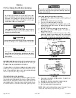
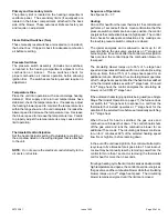
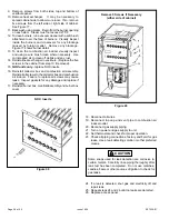
Page 30: ... Never use tools If the switch will not turn or if the control switch will not move by hand do not try to repair it Placing the furnace into operation These units are equipped with an automatic ignition system Do not attempt to manually light burners on these furnaces Each time the thermostat calls for heat the burners will automatically light The ignitor does not get hot when there is no call for...

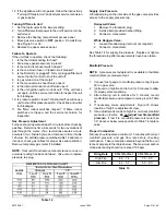
Page 31: ...nifold pressure matches table 14 and rate is incorrect check gas orifices for proper size and restriction Remove temporary gas meter if installed NOTE Shut unit off and remove manometer as soon as an accurate reading has been obtained Take care to replace pressure tap plug Supply Line Pressure A threaded plug on the inlet side of the gas valve provides access to the supply pressure tap Honeywell V...

Page 32: ... as an accurate reading has been obtained Take care to replace pressure tap plug WARNING Manifold Pressure Settings 1 This is the only permissible derate for these units 2 Natural gas high altitude orifice kit required 3 A natural to L P propane gas changeover kit is necessary to convert this unit Refer to the changeover kit installation instruction for the conversion procedure NOTE Units may be i...

Page 33: ... for adequate combustion air by making sure the low fire pressure switch contacts are closed The igniter energizes and is allowed to warm up for 20 seconds before the gas valve energizes on 1st stage and burners ignite 45 seconds after the control confirms ignition has occurred the control drops the combustion blower to low speed The circulating blower ramps up to 50 of 1st stage heat speed and op...

Page 34: ...ating blower motor runs at 50 of the selected cooling CFM until switched off When the call for fan is turned off the control de energizes the circulating blower Cooling The unit is set up at the factory for single stage cooling For two stage cooling operation clip the jumper wire located between the Y to Y2 terminals on the integrated ignition blower control board If the active dehumidification fe...

Page 35: ...ue 1624 Figure 36 Single Stage Cooling Figure 33 1st Stage 2nd Stage W1 W2 Heat Call Figure 34 High Heat W2 Call Figure 35 Call for Fan Percentage of High Stage Cooling Figure 37 Two Stage Cooling Percentage of High Stage Cooling ...

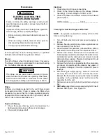
Page 36: ...all connections for tightness and to make sure there is no blockage 2 Check unit for proper draft Electrical 1 Check all wiring for loose connections 2 Check for the correct voltage at the furnace furnace operating Correct voltage is 120VAC 10 3 Check amp draw on the blower motor with inner blower panel in place Unit Nameplate____________Actual______________ Cleaning the Heat Exchanger and Burners...

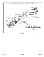
Page 37: ...507335 01 Page 37 of 44 Issue 1624 Burner Combustion Air Inducer Assembly and Heat Exchanger Removal Figure 38 ...

Page 38: ...nserts 16 Reinstall collector box and combustion air assembly Reinstall all screws to the collector box and combustion air inducer Failure to replace all screws may cause leaks Inspect gaskets for any damage and replace if necessary 17 Reinstall burner box manifold assembly and burner box cover 18 Reconnect all wires 19 Reconnect top cap and vent pipe to combustion air inducer outlet 20 Reconnect ...

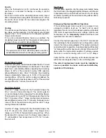
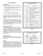
Page 39: ...are presented in Table 16 Fault Code History Button The control stores the last five fault codes in memory A pushbutton switch is located on the control see Figure 42 on page 42 When the pushbutton switch is pressed and released the control flashes the stored fault codes The most recent fault code is flashed first the oldest fault code is flashed last To clear the fault code history press and hold...

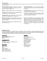
Page 40: ...r Burners Must be inspected for rust dirt or signs of water Vent pipe Must be inspected for signs of water damaged or sagging pipe or disconnected joints Unit appearance Must be inspected for rust dirt signs of water burnt or damaged wires or components Blower access panel Must be properly in place and pro vide a seal between the return air and the room where the furnace is installed Return air du...

Page 41: ...507335 01 Page 41 of 44 Issue 1624 Wiring Diagram Figure 41 ...

Page 42: ...507335 01 Page 42 of 44 Issue 1624 Typical Field Wiring Diagram Figure 42 ...

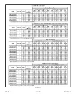
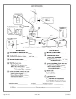
Page 43: ...507335 01 Page 43 of 44 Issue 1624 Start Up Performance Check List UNIT SET UP ...

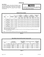
Page 44: ...507335 01 Page 44 of 44 Issue 1624 UNIT OPERATION ...

Reviews: