508187-01
Issue 2116
Page 12 of 51
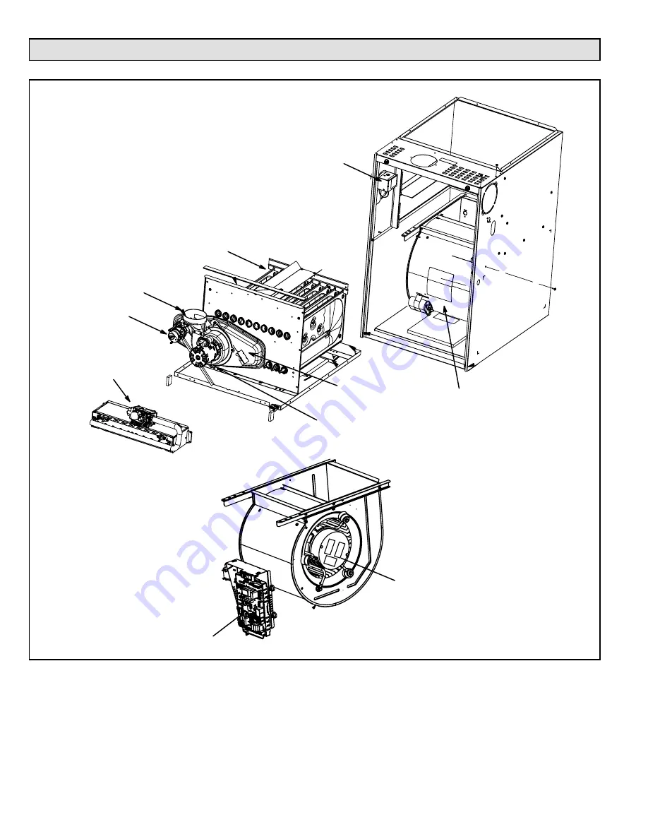
Parts Arrangement
Figure 1.
Combustion Air
Pressure Switch
Combustion Air
Inducer
Gas Valve and Manifold
Assembly
Limit Switch
(under collector box)
Collector Box
Heat Exchanger
Indoor Blower and Motor Assembly
(installed in cabinet)
Make Up Box
Constant Torque Indoor Blower Motor
(removed from cabinet)
Two-Stage Integrated Control


