background image

507868-01

Page 15 of 48

Issue 1912

Venting Practices

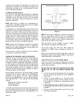
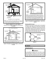
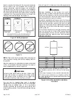
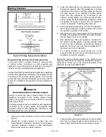
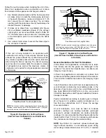
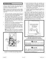
Figure 20. Piping Suspension Guidelines

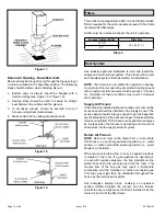
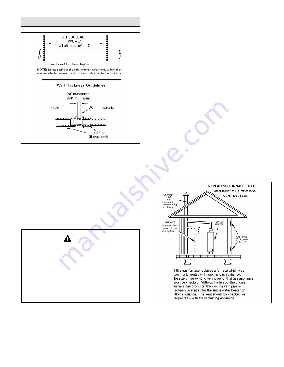
Removal of the Furnace from Common Vent

In  the  event  that  an  existing  furnace  is  removed  from 

a  venting  system  commonly  run  with  separate  gas 

appliances, the venting system is likely to be too large to 

properly vent the remaining attached appliances.

Conduct the following test while each appliance is operating 

and the other appliances (which are not operating) remain 

connected to the common venting system. If the venting 

system has been installed improperly, you must correct the 

system as indicated in the general venting requirements 

section.

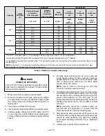
CARBON MONOXIDE POISONING HAZARD

Failure  to  follow  the  steps  outlined  below  for  each 

appliance  connected  to  the  venting  system  being 

placed into operation could result in carbon monoxide 

poisoning or death.
The following steps shall be followed for each appliance 

connected  to  the  venting  system  being  placed  into 

operation, while all other appliances connected to the 

venting system are not in operation.

 DANGER

1.  Seal  any  unused  openings  in  the  common  venting 

system.

2.  Inspect  the  venting  system  for  proper  size  and 

horizontal pitch. Determine that there is no blockage, 

restriction,  leakage,  corrosion,  or  other  deficiencies 

which could cause an unsafe condition.

3. 

Close all building doors and windows and all doors 

between the space in which the appliances remaining 

connected to the common venting system are located 

and  other  spaces  of  the  building.  Turn  ON  clothes 

dryers  and  any  appliances  not  connected  to  the 

common venting system. Turn ON any exhaust fans, 

such as range hoods and bathroom exhausts, so they 

will  operate  at  maximum  speed.  Do  not  operate  a 

summer exhaust fan. Close fireplace dampers.

4.  Follow the lighting instructions. Turn ON the appliance 

that is being inspected. Adjust the thermostat so that 

the appliance operates continuously.

5.  After the main burner has operated for 5 minutes, test 

for leaks of flue gases at the draft hood relief opening. 

Use the flame of a match or candle.

6.  After  determining  that  each  appliance  connected  to 

the common venting system is venting properly, (step 

3)  return  all  doors,  windows,  exhaust  fans,  fireplace 

dampers,  and  any  other  gas  burning  appliances  to 

their previous mode of operation.

7.  If  a  venting  problem  is  found  during  any  of  the 

preceding tests, the common venting system must be 

modified to correct the problems.

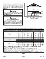
Resize the common venting system to the minimum vent 

pipe  size  determined  by  using  the  appropriate  tables  in 

Appendix  G.  These  are  in  the  current  standards  of  the 

National Fuel Gas Code ANSI Z223.1.

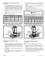
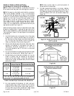
Figure 21. 

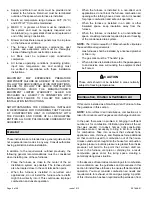
1.  In areas where piping penetrates joist or interior walls, 

hole must be large enough to allow clearance on all 

sides of pipe through center of hole using a hanger.

Summary of Contents for 92G1DFE

Page 1: ...mage personal injury or loss of life Installation and service must be performed by a licensed professional installer or equivalent service agency or the gas supplier WARNING As with any mechanical equipment personal injury can result from contact with sharp sheet metal edges Be careful when you handle this equipment CAUTION Table of Contents Unit Dimensions 2 Parts Arrangement 3 Gas Furnace 4 Ship...

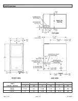
Page 2: ...507868 01 Page 2 of 48 Issue 1912 Unit Dimensions Model A93DF1E 92G1DFE A B C in mm in mm in mm 045 12 070 12 17 1 2 446 16 3 8 416 16 406 090 16 21 533 19 7 8 504 19 1 2 495 ...

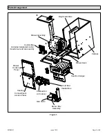
Page 3: ... Heating Compartment Access Panel Blower Access Panel Cold End Header Box Control Box includes integrated control transformer and door switch Blower Assembly Bag Assemblies Cabinet Blower Deck Heat Exchanger Combustion Air Inducer E X H A U S T IN T A K E Parts Arrangement ...

Page 4: ...eaded street elbow Check equipment for shipping damage If you find any damage immediately contact the last carrier Please refer to specification sheets for available accessories Safety Information DANGER OF EXPLOSION There are circumstances in which odorant used with LP Propane gas can lose its scent In case of a leak LP Propane gas will settle close to the floor and may be difficult to smell An L...

Page 5: ...t must be equipped to prevent operation of either the heating or the cooling unit unless it is in the full HEAT or COOL setting When installed this furnace must be electrically grounded according to local codes In addition in the United States installation must conform with the current National Electric Code ANSI NFPA No 70 The National Electric Code ANSI NFPA No 70 is available from the following...

Page 6: ...rafts might blow directly into it This could cause improper combustion and unsafe operation When the furnace is installed in a non direct vent applications do not block the furnace combustion air opening with clothing boxes doors etc Air is needed for proper combustion and safe unit operation When the furnace is installed in an attic or other insulated space keep insulation away from the furnace W...

Page 7: ...combustion and ventilation depend largely on whether the furnace is installed in an unconfined or a confined space Unconfined Space An unconfined space is an area such as a basement or large equipment room with a volume greater than 50 cubic feet 1 42 m per 1 000 Btu 29 kW per hour of the combined input rating of all appliances installed in that space This space also includes adjacent rooms which ...

Page 8: ...nsion of rectangular air ducts shall be no less than 3 inches 75 mm In calculating free area the blocking effect of louvers grilles or screens must be considered If the design and free area of protective covering is not known for calculating the size opening required it may be assumed that wood louvers will have 20to 25 percent free area and metal louvers and grilles will have 60 to 75 percent fre...

Page 9: ...d Space all Air from Outside Shipping Bolt Removal Units with 1 2 hp and 3 4 hp blower motors are equipped with three flexible legs and one rigid leg The rigid leg is equipped with a shipping bolt and a flat white plastic washer rather than the rubber mounting grommet used with a flexible mounting leg See Figure 11 The bolt and washer must be removed before the furnace is placed into operation Aft...

Page 10: ...Do not drag the unit across the floor in the downflow position Floor and furnace flange damage will result Refer to Figure 14 for clearances in downflow applications Improper installation of the furnace can result in personal injury or death Combustion and flue products must never be allowed to enter the return air system or air in the living space Use sheet metal screws and joint tape to seal ret...

Page 11: ... 2 After opening is cut set the combustible flooring base into opening 3 Check fiberglass strips on the combustible flooring base to make sure they are properly glued and positioned 4 Lower supply air plenum into the combustible flooring base until plenum flanges seal against fiberglass strips NOTE Be careful not to damage fiberglass strips Check for a tight seal 5 Set the furnace over the plenum ...

Page 12: ...external static pressure which exceeds 0 5 inches w c Operation at these conditions may result in improper limit operation Supply Air Plenum If the furnace is installed without a cooling coil a removable access panel should be installed in the supply air duct The access panel should be large enough to permit inspection by reflected light of the heat exchanger for leaks after the furnace is install...

Page 13: ...rces of ignition Do not use excessive amounts of solvent cement when making joints Good ventilation should be maintained to reduce fire hazard and to minimize breathing of solvent vapors Avoid contact of cement with skin and eyes CAUTION The exhaust and intake connections are made of PVC Use PVC primer and solvent cement when using PVC vent pipe When using ABS vent pipe use transitional solvent ce...

Page 14: ...s Termination kits 44W92 and 44W93 are approved for use in Canadian installations to meet CSAB149 The 44W92 Concentric kit is provided with a 1 1 2 accelerator which must be installed on the exhaust outlet when this kit is used with this furnace NOTE When using 1 1 2 piping and terminating with a flush mount kit or concentric kit the pipe must be transitioned to 2 pipe before attaching to the flus...

Page 15: ... condition 3 Close all building doors and windows and all doors between the space in which the appliances remaining connected to the common venting system are located and other spaces of the building Turn ON clothes dryers and any appliances not connected to the common venting system Turn ON any exhaust fans such as range hoods and bathroom exhausts so they will operate at maximum speed Do not ope...

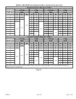
Page 16: ...outdoors and flue gases are discharged outdoors Intake and exhaust pipe sizing Size pipe according to Table 6 and Table 7A through Table 7B Table 6 lists the minimum vent pipe lengths permitted Table 7A and Table 7B list the maximum pipe lengths permitted Regardless of the diameter of pipe used the standard roof and wall terminations described in section Exhaust Piping Terminations should be used ...

Page 17: ...16 65 50 13 97 97 78 8 26 11 60 45 n a 92 92 73 9 21 n a 55 40 87 87 68 10 16 50 35 82 82 63 Concentric Termination Elevation 0 10 000 ft Number of 90 Elbows Used 1 1 2 Pipe 2 Pipe 2 1 2 Pipe 3 Pipe Model Model Model Model 045 070 090 045 070 090 045 070 090 045 070 090 1 15 10 n a 53 38 22 90 70 39 111 111 104 2 10 n a 48 33 17 85 65 34 106 106 99 3 n a 43 28 12 80 60 29 101 101 94 4 38 23 n a 75...

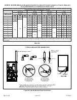
Page 18: ...9 11 45 60 67 67 48 10 6 40 55 62 62 43 NOTE Additional vent pipe and elbows used to terminate the vent pipe outside the structure must be included in the total vent length calculation Figure 23 Typical Exhaust Pipe Connections TYPICAL EXHAUST PIPE CONNECTIONS Pipe size determined in table 7 2 TOP VIEW EXHAUST INTAKE 2 2 2 2 or TRANSITION 3 2 2 1 1 2 or TRANSITION EXHAUST EXHAUST NOTE 1 1 2 Vent P...

Page 19: ...o the furnace from the surrounding space the indoor air quality must be considered Guidelines listed in Combustion Dilution and Ventilation Air section must be followed Follow the next two steps when installing the unit in Direct Vent applications where combustion air is taken from outdoors and flue gases are discharged outdoors The provided air intake screen must not be used in direct vent applic...

Page 20: ...ir to Outside Roof Terminated Exhaust Pipe Furnace Ventilation Louvers Crawl Space Intake Debris Screen Provided Inlet Air Minimum 12 in 305mm above Crawl Space Floor Coupling or 3 in to 2 in Transition Field Provided See Maximum Vent Lengths table NOTE The inlet and outlet air openings shall each have a free area of at least one square inch per 4 000 Btu 645mm2 per 1 17kW per hour of the total in...

Page 21: ... in Unconditioned Space for Winter Design Temperatures Single Stage High Efficiency Furnace Winter Design Temperatures1 ºF ºC Vent Pipe Diameter Unit Input Size 045 070 090 32 to 21 0 to 6 PVC 2 PP PVC 2 PP PVC 2 PP 1 1 2 in 25 N A 20 N A N A N A 2 in 18 16 31 28 50 48 2 1 2 in 13 N A 24 N A 42 N A 3 in 9 9 18 18 35 35 20 to 1 7 to 17 1 1 2 in 15 N A 20 N A N A N A 2 in 9 8 18 16 32 29 2 1 2 in 5 ...

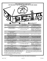
Page 22: ...earance under veranda porch deck or balcony 12 Equal to or greater than soffit depth 3 feet 9m 12 3 feet 9m within a height 15 feet 4 5m above the meter regulator assembly 3 feet 9m 6 inches 152mm for appliances 10 000 Btuh 3kw 12 inches 305mm for appliances 10 000 Btuh 3kw and 100 000 Btuh 30kw 36 inches 9m for appliances 100 000 Btuh 30kw 3 feet 9m above if within 10 feet 3m horizontally 6 feet ...

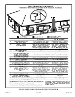
Page 23: ...es 152mm for appliances 10 000 pliances 10 000 Btuh 3kw and 50 000 pliances 50 000 Btuh 15kw 6 inches 152mm for appliances 10 000 Btuh 3kw 12 inches 305mm for appliances 10 000 Btuh 3kw and 100 000 Btuh 30kw 36 inches 9m for appliances 100 000 Btuh 30kw 3 feet 9m above if within 10 feet 3m horizontally 6 feet 1 8m 7 feet 2 1m 12 inches 305mm 1 In accordance with the current ANSI Z223 1 NFPA 54 Nat...

Page 24: ...ation is 3 76 mm on roof terminations and 6 152 mm on side wall terminations 3 On roof terminations the intake piping should terminate straight down using two 90 elbows see Figure 31 4 Exhaust piping must terminate straight out or up as shown A reducer may be required on the exhaust piping at the point where it exits the structure to improve the velocity of exhaust away from the intake piping See ...

Page 25: ...ENT PIPE SIZE TO TERMINATION 1 1 2 38mm accelerator provided on 71M80 44W92 12 305mm INTAKE AIR EXHAUST VENT Figure 36 Direct Vent Concentric Wall Termination 12 305mm Min above grade or average snow accumulation INTAKE AIR INTAKE AIR INTAKE AIR OUTSIDE WALL GRADE CLAMP Not Furnished FIELD PROVIDED REDUCER MAY BE REQUIRED TO ADAPT LARGER VENT PIPE SIZE TO TERMINATION EXHAUST VENT 1 1 2 38mm accele...

Page 26: ...n tee should be connected to the 2 or 3 PVC flue pipe as shown in the illustration Do not use an accelerator in applications that include an exhaust termination tee The accelerator is not required 2 As required Flue gas may be acidic and may adversely affect some building materials If a side wall vent termination is used and flue gases will impinge on the building materials a corrosion resistant s...

Page 27: ...n Figure 42 When exhaust piping must be run up an outside wall any reduction in exhaust pipe size must be done after the final elbow Figure 40 Non Direct Vent Roof Termination Kit UNCONDITIONED ATTIC SPACE 3 76MM OR 2 51MM PVC PROVIDE SUPPORT FOR EXHAUST LINES 12 305MM ABOVE AVE SNOW ACCUMULATION SIZE PER EXHAUST PIPE TERMINATION SIZE REDUCTION TABLE Figure 41 Non Direct Vent Field Supplied Wall T...

Page 28: ...Termination Drain Trap assembled Figure 44 Kit 51W18 USA 15Z70 Canada Parts Identification and Assembly Exhaust from Furnace To Termination Exhaust from Furnace To Termination Kit 51W18 is shown Figure 45 Crawl Space Vent Pipe Drain Trap Assembled Incorrectly Figure 46 Upflow or Downflow Furnace with Exhaust through Crawl Space KIT 51W18 USA Basement Floor To Termination 1 2 PVC to Code Approved D...

Page 29: ...condensate drain Tubing must be 1 1 4 ODx1 ID and should be attached to the drain on the trap using a hose clamp Figure 47 Condensate Trap and Plug Locations 5 Figure 49 shows the furnace and evaporator coil using a separate drain If necessary the condensate line from the furnace and evaporator coil can drain together See Figure 50 The field provided vent must be a minimum 1 to a maximum 2 length ...

Page 30: ...507868 01 Page 30 of 48 Issue 1912 Figure 49 Evaporator Coil Using a Separate Drain Figure 50 Evaporator Coil Using a Common Drain Figure 51 Condensate Trap with Optional Overflow Switch ...

Page 31: ...507868 01 Page 31 of 48 Issue 1912 Figure 52 Trap Drain Assembly Using 1 2 PVC or 3 4 PVC ...

Page 32: ...rip leg in vertical pipe runs to serve as a trap for sediment or condensate 5 A 1 8 N P T plugged tap or pressure post is located on the gas valve to facilitate test gauge connection See Figure 53 6 In some localities codes may require installation of a manual main shut off valve and union furnished by installer external to the unit Union must be of the ground joint type Compounds used on threaded...

Page 33: ...54 118 3 34 110 3 11 103 2 92 1 25 4 1 049 26 645 680 19 25 465 13 17 375 10 62 320 9 06 285 8 07 260 7 36 240 6 80 220 6 23 205 5 80 195 5 52 1 1 4 31 75 1 380 35 052 1400 39 64 950 26 90 770 21 80 660 18 69 580 16 42 530 15 01 490 13 87 460 13 03 430 12 18 400 11 33 1 1 2 38 1 1 610 40 894 2100 59 46 460 41 34 1180 33 41 990 28 03 900 25 48 810 22 94 750 21 24 690 19 54 650 18 41 620 17 56 2 50 ...

Page 34: ... long enough to facilitate future removal of blower for service Complete the wiring connections to the equipment Use the provided unit wiring diagram and the field wiring diagram shown in Figure 58 Use 18 gauge wire or larger that is suitable for Class II rating for thermostat connections Electrically ground the unit according to local codes or in the absence of local codes according to the curren...

Page 35: ...or blower will run continuously on the heating speed when there is no cooling or heating demand 2 When the furnace is running in the heating mode the indoor blower will run on the heating speed 3 When there is a cooling demand the indoor blower will run on the cooling speed Generator Use Voltage Requirements The following requirements must be kept in mind when specifying a generator for use with t...

Page 36: ...507868 01 Page 36 of 48 Issue 1912 Figure 59 Typical Wiring Diagram ...

Page 37: ... next to the floor because some gas is heavier than air and will settle on the floor The gas valve on the unit is equipped with a gas control switch lever Use only your hand to move switch Never use tools If the switch will not move by hand do not try to repair it Force or attempted repair may result in a fire or explosion Placing the Furnace into Operation This furnace is equipped with an automat...

Page 38: ...llow the gas supplier s instructions If you do not smell gas go to next step 8 Move gas valve switch to ON See Figure 61 9 Replace the heating compartment access panel 10 Turn on all electrical power to the unit 11 Set the thermostat to desired setting NOTE When unit is initially started steps 1 through 11 may need to be repeated to purge air from gas line 12 If the appliance will not operate foll...

Page 39: ...rt unit and allow 5 minutes for unit to reach steady state 3 While waiting for the unit to stabilize observe the flame Flame should be stable and should not lift from burner Natural gas should burn blue 4 After allowing unit to stabilize for 5 minutes record manifold pressure and compare to value given in Table 13 NOTE Shut unit off and remove manometer as soon as an accurate reading has been obta...

Page 40: ... Kit All 11K50 73W80 51W01 11K45 Conversion requires installation of a gas valve regulator spring which is provided with the gas conversion Kit LP Kits include low line pressure switch A93DF1E 92G1DFE Pressure Switch at Varying Altitudes Capacity 0 4500 ft 0 1371m 4501 7500 ft 1371 2286m 7501 10000 ft 2286 3048m 045 No Change 11U65 11U66 070 090 Pressure switch is factory set No adjustment necessa...

Page 41: ... 2 Visually inspect the venting system for proper size and horizontal pitch Determine there is no blockage or restriction leakage corrosion or other deficiencies which could cause an unsafe condition 3 To the extent that it is practical close all building doors and windows and all doors between the space in which the appliances connected to the venting system are located and other spaces of the bu...

Page 42: ...mostat Heat Anticipation Set the heat anticipator setting if adjustable according to the amp draw listed on the wiring diagram that is attached to the unit Electrical 1 Check all wiring for loose connections 2 Check for the correct voltage at the furnace with furnace operating Correct voltage is 120 VAC 10 3 Check amp draw on the blower motor with the blower compartment access panel in place Motor...

Page 43: ...0 10 1380 351 1265 276 1140 202 860 109 700 73 0 20 1345 360 1240 285 1090 208 810 119 645 79 0 30 1325 371 1215 291 1060 218 770 124 590 84 0 40 1295 380 1175 302 1025 228 710 132 530 91 0 50 1260 392 1135 318 985 236 670 138 490 94 0 60 1235 402 1105 320 955 247 620 146 440 102 0 70 1185 411 1080 333 910 254 585 152 395 106 0 80 N A N A 1040 342 865 261 540 157 340 113 A93DF1E090C16A 92G1DF090CE...

Page 44: ...e____________Actual____________ Winterizing and Condensate Trap Care 1 Turn off power to the furnace 2 Have a shallow pan ready to empty condensate water 3 Remove the clean out cap from the condensate trap and empty water Inspect the trap then reinstall the clean out cap Cleaning Heat Exchanger If cleaning the heat exchanger becomes necessary follow the below procedures and refer to Figure 1 when ...

Page 45: ...p in center of burner ports 34 Reinstall gas valve manifold assembly Reconnect gas supply line to gas valve 35 Reconnect 2 wires to gas valve 36 Replace the blower compartment access panel 37 Refer to instruction on verifying gas and electrical connections when re establishing supplies 38 Follow lighting instructions to light and operate furnace for 5 minutes to ensure that heat exchanger is clean...

Page 46: ...ode limit switch open longer than 3 minutes 8 Flashes Rollout switch open 9 Flashes Pressure switch failed to close or opened during heat demand 10 Flashes Watchguard Pressure switch opened 5 times during one heat demand 11 Flashes Pressure switch stuck closed prior to activation of combustion air inducer 12 Flashes Flame sensed without gas valve energized 13 Flashes Low line voltage 1 A heartbeat...

Page 47: ...s Problems detected during the inspection may make it necessary to temporarily shut down the furnace until the items can be repaired or replaced Instruct the homeowners to pay attention to their furnace Situations can arise between annual furnace inspections that may result in unsafe operation For instance items innocently stored next to the furnace may obstruct the combustion air supply This coul...

Page 48: ...m height of eight 8 feet above grade directly in line with the exhaust vent terminal for the horizontally vented gas fueled heating appliance or equipment The sign shall read in print size no less than one half 1 2 inch in size GAS VENT DIRECTLY BELOW KEEP CLEAR OF ALL OBSTRUCTIONS 4 INSPECTION The state or local gas inspector of the side wall horizontally vented gas fueled equipment shall not app...

Reviews: