507868-01
Page 18 of 48
Issue 1912
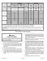
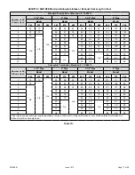
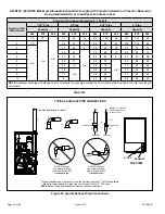
Table 7B.
A93DF1E / 92G1DFE Maximum Allowable Exhaust Vent Length with Furnace Installed in a Closet or Basement
Using Ventilated Attic or Crawl Space for Intake in Feet
Standard Termination at Elevation 0 - 10,000 ft
Number of 90°
Elbows Used
1-1/2" Pipe
2" Pipe
2-1/2" Pipe
3" Pipe
Capacity
Capacity
Capacity
Capacity
045
070
090
045
070
090
045
070
090
045
070
090
1
15
10
n/a
51
36
14
85
100
28
107
107
88
2
10
n/a
46
31
9
80
95
23
102
102
83
3
n/a
41
26
4
75
90
18
97
97
78
4
36
21
n/a
70
85
13
92
92
73
5
31
16
65
80
8
87
87
68
6
26
11
60
75
n/a
82
82
63
7
21
6
55
70
77
77
58
8
16
n/a
50
65
72
72
53
9
11
45
60
67
67
48
10
6
40
55
62
62
43
NOTE
: Additional vent pipe and elbows used to terminate the vent pipe outside the structure must be included in the total vent length
calculation.
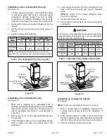
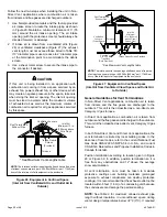
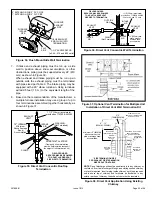
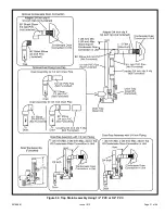
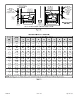
Figure 23. Typical Exhaust Pipe Connections
TYPICAL EXHAUST PIPE CONNECTIONS
Pipe size determined in table 7.
2”
TOP VIEW
EXHAUST
INTAKE
2”
2”
2”
2”
or
TRANSITION
3”
*2”
**2”
1-1/2”
or
TRANSITION
EXHAUST
EXHAUST
NOTE
: 1-1/2” Vent Pipe
Diameter Allowed Only
on 045/070 Units
DO NOT transition
from larger to smaller
pipe in horizontal runs
of
exhaust pipe
.
EXHAUST
DO NOT transition
from smaller to larger
pipe in horizontal runs
of
exhaust pipe
.
EXHAUST
* When transitioning up in pipe size, use the shortest length of 2” PVC pipe possible.
** When transitioning down in pipe size, use at least 1 foot of 2" PVC pipe.
NOTE
: Exhaust pipe and intake pipe must be the same diameter.

