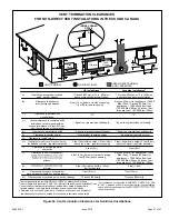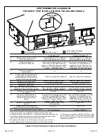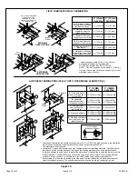
508297-01
Page 16 of 57
Issue 2219
6. Promptly apply solvent cement to end of pipe and
inside socket surface of fitting. Cement should be
applied lightly but uniformly to inside of socket. Take
care to keep excess cement out of socket. Apply
second coat to end of pipe.
7. Immediately after applying last coat of cement to pipe,
and while both inside socket surface and end of pipe
are wet with cement, forcefully insert end of pipe into
socket until it bottoms out. Turn PVC pipe 1/4 turn
during assembly (but not after pipe is fully inserted) to
distribute cement evenly. Do not turn ABS or cellular
core pipe.
NOTE:
Assembly should be completed within 20
seconds after last application of cement. Hammer
blows should not be used when inserting pipe.
8. After assembly, wipe excess cement from pipe at end
of fitting socket. A properly made joint will show a bead
around its entire perimeter. Any gaps may indicate
an improper defective assembly due to insufficient
solvent.
9. Handle joints carefully until completely set.
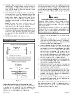
Venting Practices
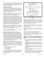
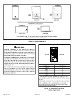
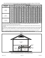
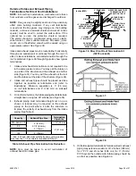
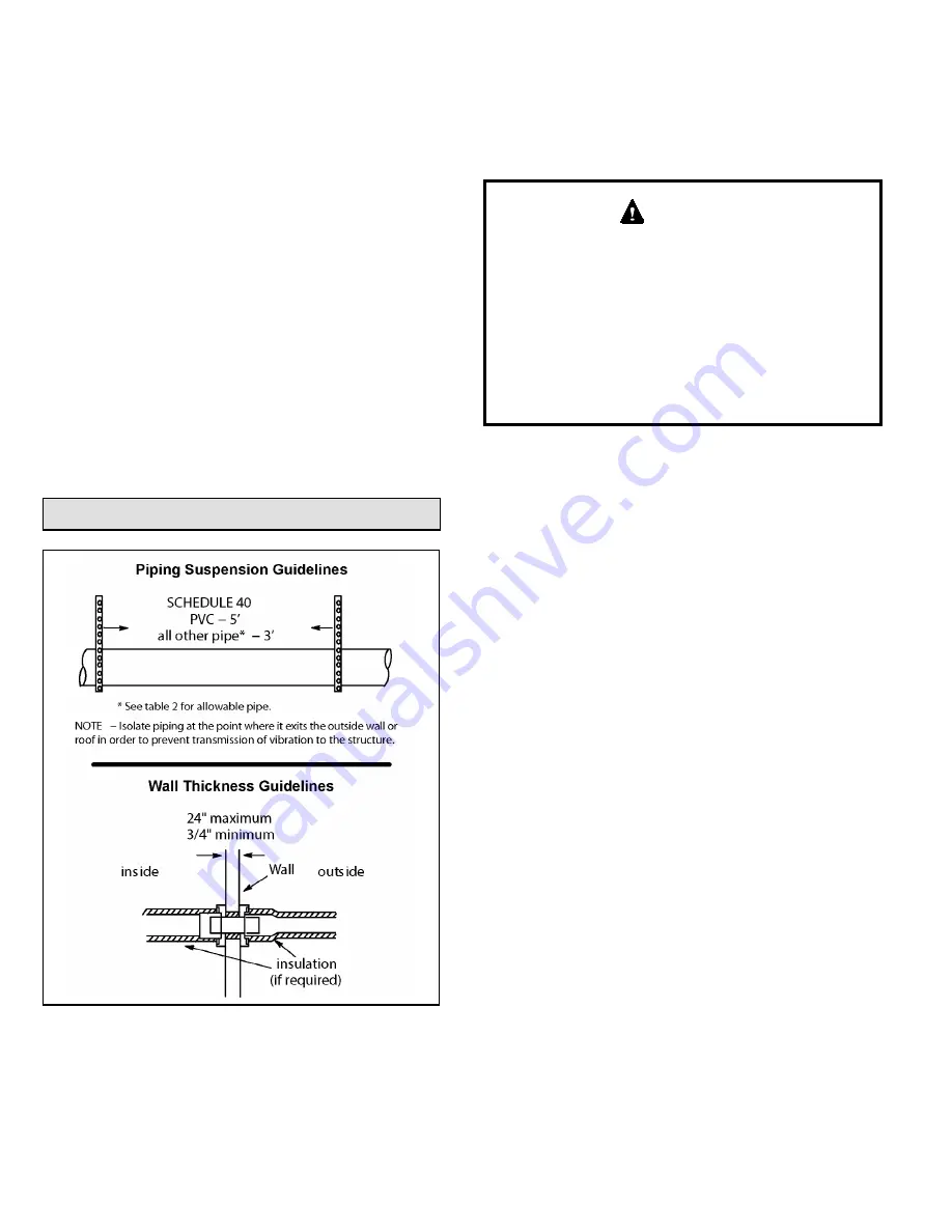
Figure 21.
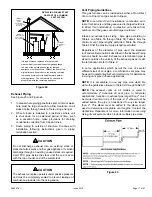
Removal of the Furnace from Common Vent
In the event that an existing furnace is removed from
a venting system commonly run with separate gas
appliances, the venting system is likely to be too large to
properly vent the remaining attached appliances.
Conduct the following test while each appliance is operating
and the other appliances (which are not operating) remain
connected to the common venting system. If the venting
system has been installed improperly, you must correct the
system as indicated in the general venting requirements
section.
CARBON MONOXIDE POISONING HAZARD
Failure to follow the steps outlined below for each
appliance connected to the venting system being
placed into operation could result in carbon monoxide
poisoning or death.
The following steps shall be followed for each appliance
connected to the venting system being placed into
operation, while all other appliances connected to the
venting system are not in operation.
WARNING
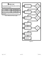
1. Seal any unused openings in the common venting
system.
2. Inspect the venting system for proper size and
horizontal pitch. Determine that there is no blockage,
restriction, leakage, corrosion, or other deficiencies
which could cause an unsafe condition.
3. Close all building doors and windows and all doors
between the space in which the appliances remaining
connected to the common venting system are located
and other spaces of the building. Turn ON clothes
dryers and any appliances not connected to the
common venting system. Turn ON any exhaust fans,
such as range hoods and bathroom exhausts, so they
will operate at maximum speed. Do not operate a
summer exhaust fan. Close fireplace dampers.
4. Follow the lighting instructions. Turn ON the appliance
that is being inspected. Adjust the thermostat so that
the appliance operates continuously.
5. After the main burner has operated for 5 minutes, test
for leaks of flue gases at the draft hood relief opening.
Use the flame of a match or candle.
6. After determining that each appliance connected to
the common venting system is venting properly, (step
3) return all doors, windows, exhaust fans, fireplace
dampers, and any other gas burning appliances to
their previous mode of operation.
7. If a venting problem is found during any of the
preceding tests, the common venting system must be
modified to correct the problems.
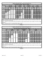
Resize the common venting system to the minimum vent
pipe size determined by using the appropriate tables in
Appendix G. (These are in the current standards of the
National Fuel Gas Code ANSI Z223.1.

