background image

508148-01

Issue 2128

Page 41 of 75

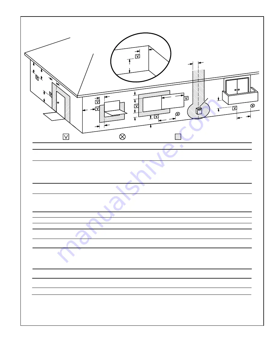
VENT TERMINATION CLEARANCES

FOR DIRECT VENT INSTALLATIONS IN THE USA AND CANADA

K

D

E

L

B

C

F

G

A

B

J

A

M

I

H

INSIDE CORNER

DETAIL

VENT TERMINAL

AIR SUPPLY INLET

AREA WHERE TERMINAL

IS NOT PERMITTED

Fixed

Closed

Operable

B

Fixed

Closed

Operable

B

B

A =

B =

C =

D =

E =
F =
G =
H =

I =

J =

K =

L =

M =

US Installations

1

Canadian Installations

2

12 inches (305mm) or 12 in. (305mm)

above average snow accumulation.

12 inches (305mm) or 12 in. (305mm)

above average snow accumulation.

Clearance above grade, veranda,

porch, deck or balcony

Clearance to window or

door that may be opened

6 inches (152mm) for appliances <10,000

pliances > 10,000 Btuh (3kw) and <50,000

pliances > 50,000 Btuh (15kw)

6 inches (152mm) for appliances <10,000

Btuh (3kw), 12 inches (305mm) for 

appliances > 10,000 Btuh (3kw) and

<100,000 Btuh (30kw), 36 inches (.9m)

for appliances > 100,000 Btuh (30kw)

Clearance to permanently

closed window

Vertical clearance to ventilated soffit 

located above the terminal within a

horizontal distance of 2 feet (610mm)

from the center line of the terminal

Clearance to unventilated soffit

Clearance to outside corner

Clearance to inside corner

tended above meter / regulator assembly

Clearance to service regulator

vent outlet

Clearance to non-mechanical air

pliance

ply inlet

Clearance above paved sidewalk or

paved driveway located on public property

Clearance under veranda, porch, deck or balcony

* 12”

*

*

* 7 feet (2.1m)

3 feet (.9m) within a height 15 feet (4.5m)

above the meter / regulator assembly

3 feet (.9m)

6 inches (152mm) for appliances <10,000

pliances > 10,000 Btuh (3kw) and <50,000

pliances > 50,000 Btuh (15kw)

6 inches (152mm) for appliances <10,000

Btuh (3kw), 12 inches (305mm) for 

appliances > 10,000 Btuh (3kw) and

<100,000 Btuh (30kw), 36 inches (.9m)

for appliances > 100,000 Btuh (30kw)

3 feet (.9m) above if within 10 feet

(3m) horizontally

6 feet (1.8m)

7 feet (2.1m)†

12 inches (305mm)‡

In accordance with the current ANSI Z223.1/NFPA 54 Natural Fuel Gas Code

In accordance with the current CSA B149.1, Natural Gas and Propane Installation Code

*For clearances not specified in ANSI Z223.1/NFPA 54 or CSA

B149.1, clearance will be  in accordance with local installation

codes  and  the  requirements  of  the  gas  supplier  and  these

installation instructions.”

 † A vent shall not terminate directly above a sidewalk or paved driveway that is located

between two single family dwellings and serves both dwellings.

 ‡ Permitted only if veranda, porch, deck or balcony is fully open on a minimum of

two sides beneath the floor. Allied Air recommends avoiding this location if possible.

* 12”

* Equal to or greater than soffit depth

* Equal to or greater than soffit depth

* Equal to or greater than soffit depth

* Equal to or greater than soffit depth

* No minimum to outside corner

* No minimum to outside corner

3 feet (.9m) within a height 15 feet (4.5m)

above the meter / regulator assembly

3 feet (.9m)

*

*12 inches (305mm)‡

Btuh (3kw), 9 inches (228mm) for ap-

Btuh (15kw), 12 inches (305mm) for ap-

Clearance to each side of center line ex-

Btuh (3kw), 9 inches (228mm) for ap-

Btuh (15kw), 12 inches (305mm) for ap-

supply inlet to building or the com-

bustion air inlet to any other ap-

Clearance to mechanical air sup-

Figure 28. 

Vent Termination Clearances 

Direct Vent Installations

Summary of Contents for A96US2V

Page 1: ...ooting Continuous Fan Sequence of Operation 75 This is a safety alert symbol and should never be ignored When you see this symbol on labels or in manuals be alert to the potential for personal injury or death Electric shock hazard Can cause injury or death Before attempting to perform any service or maintenance turn the electrical power to unit OFF at disconnect switch es Unit may have multiple po...

Page 2: ... 96 0 4 1 2 120 60 1 15 10 1 40 165 A96US2V090C20S 57 000 55 000 88 000 85 000 96 0 5 1 2 120 60 1 20 12 8 40 166 A96US2V110C16S 72 000 70 000 110 000 105 000 96 0 4 1 2 120 60 1 15 10 1 40 173 A96US2V110C20S 72 000 70 000 110 000 106 000 96 0 5 1 2 120 60 1 20 12 8 40 174 A96US2V135D20S 88 000 84 000 132 000 126 000 96 0 5 1 2 120 60 1 20 12 8 40 188 Note For vent length and clearances to combust...

Page 3: ... 6 Default 6 12 18 24 18 12 6 Default 6 12 18 24 800 858 917 975 1034 1092 1151 1209 861 924 987 1050 1113 1176 1239 1302 FIRST STAGE COOLING SCFM SECOND STAGE COOLING SCFM Speed Low Med Low Med High High Low Med Low Med High High 10 605 743 853 963 880 1045 1210 1375 Default 550 675 775 875 800 950 1100 1250 10 495 608 698 788 720 855 990 1125 A96US2V090C16S Motor Size 3 4 HP Blwr Size 11 x 11 LO...

Page 4: ... Default 6 12 18 24 18 12 6 Default 6 12 18 24 1005 1078 1152 1225 1299 1372 1446 1519 1333 1430 1528 1625 1723 1820 1918 2015 FIRST STAGE COOLING SCFM SECOND STAGE COOLING SCFM Speed Low Med Low Med High High Low Med Low Med High High 10 935 1073 1238 1403 1320 1540 1760 2008 Default 850 975 1125 1275 1200 1400 1600 1825 10 765 878 1013 1148 1080 1260 1440 1643 A96US2V135D20S Motor Size 1 HP Blwr...

Page 5: ...2 17 5 B Width 68W63 21 0 C Width 68W64 24 5 D Width Night Service Kits 89W53 Two stage Horizontal Suspension Kit 51W10 80 90 Kit Flush Mount Termination 90 Furnaces only 51W11 2 3 0 Vent US 51W12 2 3 0 Vent ULC S636 Compliant Canada Concentric Vent Kit 90 Furnaces only 71M80 1 1 2 Vent Version US 44W92 1 1 2 and 2 Vent Version Canada 69M29 2 Vent Version US 60L46 3 Vent Version US 44W93 3 Vent Ve...

Page 6: ...508148 01 Issue 2128 Page 6 of 75 Parts Arrangement Figure 1 ...

Page 7: ...d all unit operation will shutdown The breaker can be manually reset by pressing the button on the face See Figure 3 PRESS TO RESET Figure 3 Circuit Breaker CB8 Shock hazard Disconnect power before servicing Integrated control is not field repairable If control is inoperable simply replace entire control Can cause injury or death Unsafe operation will result if repair is attempted WARNING Integrat...

Page 8: ... to low fire After the 15 second pre purge period the ignitor warms up for 20 seconds after which the gas valve opens for a 4 second trial for ignition The ignitor remains energized during the trial until flame is sensed If ignition is not proved during the 4 second period the control will try four more times with an inter purge and warm up time between trials of 35 seconds After a total of five t...

Page 9: ...508148 01 Issue 2128 Page 9 of 75 Figure 4 Integrated Control ...

Page 10: ...100 OFF OPTION C OFF 100 100 OFF OPTION D OFF 100 OFF DEFAULT 10 10 HIGH SPEED MEDIUM HIGH SPEED MEDIUM LOW SPEED LOW SPEED 7 PROTECTIVE PLASTIC FILM ON DIP SWITCHES MAY BE REMOVED FOR EASE IN SETTING OF DIP SW CUT ON BOARD LINK SOLDER TRACE COMPLETELY THROUGH BOTH LAYERS ON THE CONTROL BOARD LINKS CUT IN ERROR INSTALL A JUMPER ON THE APPROPRIATE TERMINALS ON THE TERMINAL STRIP 1 ON ON ON ON 90 SE...

Page 11: ...access the flame signal mode The integrated control will display the flame current on seven segment LED in in micro amps uA Flame signal mode is exited after any of the following Power is reset Pressing and holding push button until 3 horizontal lines are displayed 10 minutes after entering the flame sense mode Program Unit Capacity Size Mode After the P is selected by releasing the push button th...

Page 12: ...ms System resumes normal operation 5 seconds after fault recovered E115 Low 24V Control will restart if the error recovers 24 Volt Power high Range is 18 to 30 Volts Check and correct voltage Check for additional power robbing equipment connected to system May require installation of larger VA transformer to be installed in furnace air handler Clears after fault recovered E120 Unresponsive device ...

Page 13: ...nstallation instruction Critical Alert Cleared after valid unit code is read following a reset remove thermostat from system while applying power and reprogramming E204 Gas valve mis wired Check gas valve operation and wiring Clears when repaired E205 Gas valve control relay contact shorted Check wiring on control and gas valve If wiring is correct replace control E207 Hot surface igniter sensed o...

Page 14: ...tral to ground to ensure good unit ground Alert clears after current heat call has been completed E274 Soft lockout Exceeded maximum number of recycles Last recycle failed due to the limit circuit opening or limit remained open longer than 3 minutes Shut down system 1 hour soft lockout Check firing rate and air flow Check for blockage Clears when heat call finishes successfully E275 Soft lockout F...

Page 15: ...een R O on integrated control with non communicating outdoor unit dual fuel model required for heat pump application Configuration link R to O needs to be restored Replace link or hardware Applicable in non communicating mode Critical Alert E401 LSOM Compressor long run cycle or low system pressure Compressor ran more that 18 hours to satisfy a single thermostat demand Critical Alert Clears the er...

Page 16: ...ve a supply air temperature between 90 and 110 F at the exact moment that the blower is de energized Longer off delay settings provide lower supply air temperatures shorter settings provide higher supply air temperatures Table 6 provides the blower off timings that will result from different switch settings Blower Off Delay Seconds Switch 3 Switch 4 60 On Off 90 Factory Off Off 120 Off On 180 On O...

Page 17: ...FM 100 CFM COMPRESSOR DEMAND 7 1 2 MIN Ramping Option C Motor runs at 100 until demand is satisfied Once demand is met motor runs at 100 for 45 seconds then ramps down to stop OFF OFF 100 CFM 100 CFM 45 SEC COMPRESSOR DEMAND Ramping Option D Motor runs at 100 until demand is satisfied Once demand is met motor ramps down to stop OFF OFF 100 CFM COMPRESSOR DEMAND Switches 11 12 and 13 Heating Mode B...

Page 18: ...DE operates independent of a Y1 thermostat demand Normal Operation 1 On On On Acceptable 24 VAC High 100 Dehumidification mode begins when humidity is greater than set point Maximum overcool from cooling setpoint is 2 F Dehumidification Call 2 On On On Demand 0 VAC High 70 Dehumidification Call ONLY 1 On On On Demand 0 VAC High 70 Thermostat will keep outdoor unit energized after cooling temperatu...

Page 19: ...ng temperature setpoint has been reached in order to maintain room humidity setpoint Maximum overcool from cooling setpoint is 2 F ROOM THERMOSTAT CALLS FOR FIRST AND SECOND STAGE COOLING BASIC MODE only active on a Y1 thermostat demand Normal Operation 1 On On On On Acceptable 24 VAC High 100 Thermostat energizes 2nd Stage and de energizes D on a call for de humidification Dehumidification Call 2...

Page 20: ...rd link W915 is a clippable connection between terminals Y1 and Y2 on the integrated control W915 must be cut if two stage cooling will be used If the link is not cut the outdoor unit will operate in second stage cooling only Indoor Blower Motor Power Choke 4 and 5 Ton Only Blower Motor B3 Figure 6 During blower operation the ECM motor emits energy that may interfere with pacemaker operation Inter...

Page 21: ...ch when applying power to the unit Motor Start Up When B3 begins start up the motor gently vibrates back and forth for a moment This is normal During this time the electronic controller is determining the exact position of the rotor Once the motor begins turning the controller slowly eases the motor up to speed this is called soft start The motor may take as long as 10 15 seconds to reach full spe...

Page 22: ...r The use of the TECMate PRO isolates the motor from the integrated control Follow the instructions provided with the kit If the motor runs do not replace Figure 8 Blower B3 Harness Connectors MOTOR with INTEGRATED CONTROLLER SHAFT P49 4 Pin P48 5 Pin J48 5 Pin Line Voltage Connector J49 4 Pin Control Connector J48 5 Pin J49 4 Pin MOTOR with INTEGRATED CONTROLLER SHAFT P49 4 Pin P48 5 Pin P48 5 Pi...

Page 23: ...s greater than 20 ohms replace the motor and control module Figure 12 Test B Heating Components Ignitor The ignitor is made of durable silicon nitride Ignitor longevity is enhanced by controlling voltage to the ignitor The integrated control provides 120 volts to the ignitor for a consistent ignition Due to this feature of the control voltage measured with a digital meter will be slightly lower To...

Page 24: ...is precisely matched to the burner input Burners can be removed as a one piece assembly for service If burner assembly has been removed it is critical to align center of each burner to the center of the clamshell when re installing See more detail in Maintenance Gas Valve The valve Figure 51 is internally redundant to assure safety shut off If the gas valve must be replaced the same type valve mus...

Page 25: ...o be replaced A proving switch connected to the combustion air inducer orifice plate is used to prove inducer operation The combustion air inducer orifice will be different for each model See Table 15 for orifice sizes The pressure switch measures the pressure differential across the combustion air inducer orifice When the proving switch opens the furnace control A92 immediately closes the gas val...

Page 26: ...the plug Reading should be between 39 and 70 ohms If the reading is correct then the problem is with the wiring between the jack plug and the control If reading is not correct the issue is the ignitor Test 3 Check ignitor for correct voltage Insert meter probes into terminals 1 and 5 use small diameter probes in order not to damage plug Check voltage during 20 second ignitor warm up period Voltage...

Page 27: ...below 1 Remove thermostat demand and allow unit to cycle off 2 Remove the tubing from the negative side red and black or red and positive side black of the pressure switch leave both connected to cold end header box 3 Take the 2 length square tubing and connect to the positive side of the pressure switch Take the 10 length square tubing and tee into the tubing from the positive side of the cold en...

Page 28: ...t is recommended during cooler weather Metal or plastic strapping may be used for vent pipe hangers Uniformly apply a liberal coat of PVC primer for PVC or use a clean dry cloth for ABS to clean inside socket surface of fitting and male end of pipe to depth of fitting socket Canadian Applications Only Pipe fittings primer and solvent cement used to vent exhaust this appliance must be certified to ...

Page 29: ...nt should be applied lightly but uniformly to inside of socket Take care to keep excess cement out of socket Apply second coat to end of pipe A96USMV VENT PIPE DIA in STANDARD CONCENTRIC Outdoor Exhaust Accelerator Dia X Length Outdoor Exhaust Accelerator Dia X Length Flush Mount Kit 1 1 2 Concentric Kit 2 Concentric Kit 3 Concentric Kit 1 1 2 X 12 2 X 12 51W11 71M80 or 44W92 69M29 or 44W92 60L46 ...

Page 30: ...acent Room If the A97US2VX furnace replaces a furnace that was commonly vented with another gas appliance the size of the existing vent pipe for that gas appliance must be checked Without the heat of the original furnace flue prod ucts the existing vent pipe is probably oversized for the single water heater or other appliance The vent should be checked for proper draw with the remaining appliance ...

Page 31: ...nt pipe size determined by using the appropriate tables in Appendix G These are in the current standards of the National Fuel Gas Code ANSI Z223 1 Exhaust Piping Figure 19 and Figure 20 Route piping to outside of structure Continue with installation following instructions given in piping termination section The A96US2V is designed for combustion air intake through an inlet in the unit s top cap In...

Page 32: ...ions outdoors 1 Use transition solvent cement or a sheet metal screw to secure the intake pipe to the inlet air connector 2 Route piping to outside of structure Continue with installation following instructions given in general guidelines for piping terminations and intake and exhaust piping terminations for direct vent sections Refer to Table 19A through Table 19B for pipe sizes Follow the next t...

Page 33: ...e the shortest length of 2 PVC pipe possible NOTE Exhaust pipe and intake pipe must be the same diameter TYPICAL INTAKE PIPE CONNECTIONS IN HORIZONTAL DIRECT OR NON DIRECT VENT APPLICATION RIGHT HAND DISCHARGE SHOWN 2 2 2 2 or 2 AIR INTAKE TRANSITION 3 2 2 When transitioning up in pipe size use the shortest length of 2 PVC pipe possible NOTE Exhaust pipe and intake pipe must be the same diameter F...

Page 34: ...nce in sizing vent pipe in these applications NOTE The exhaust collar on all models is sized to accommodate 2 Schedule 40 vent pipe In horizontal applications any transition to exhaust pipe larger than 2 must be made in vertical runs of the pipe Therefore a 2 elbow must be added before the pipe is transitioned to any size larger than 2 This elbow must be added to the elbow count used to determine ...

Page 35: ...tal in exhaust or intake terminations Doing so will cause freeze ups and may block the terminations IMPORTANT Model Min Vent Length All 15 ft or 5 ft plus 2 elbows or 10 ft plus 1 elbow Any approved termination may be added to the minimum length listed Table 18 Minimum Vent Pipe Lengths Use the following steps to correctly size vent pipe diameter 045 070 090 110 or 135 btuh Standard or Concentric ...

Page 36: ...6 21 70 70 48 13 93 92 73 73 69 10 31 16 65 65 43 8 88 87 68 68 64 Standard Termination Elevation 4500 10 000 ft Number of 90 Elbows Used 1 1 2 Pipe 2 Pipe 2 1 2 Pipe 3 Pipe Model Model Model Model 45 70 90 110 135 45 70 90 110 135 45 70 90 110 135 45 70 90 110 135 1 25 20 n a n a n a 76 61 39 n a n a 110 110 88 53 n a 133 132 113 113 109 2 20 15 71 56 34 105 105 83 48 128 127 108 108 104 3 15 10 ...

Page 37: ...8 13 60 60 44 9 76 76 69 69 60 10 23 8 55 55 39 n a 71 71 64 64 55 Concentric Termination Elevation 4 501 10 000 ft Number of 90 Elbows Used 1 1 2 Pipe 2 Pipe 2 1 2 Pipe 3 Pipe Model Model Model Model 45 70 90 110 135 45 70 90 110 135 45 70 90 110 135 45 70 90 110 135 1 20 15 n a n a n a 68 53 37 n a n a 100 100 84 49 n a 116 116 109 109 100 2 15 10 63 48 32 95 95 79 44 111 111 104 104 95 3 10 n a...

Page 38: ... 53 49 10 21 6 50 50 28 68 67 48 48 44 Standard Termination at Elevation 4500 10 000 ft Number of 90 Elbows Used 1 1 2 Pipe 2 Pipe 2 1 2 Pipe 3 Pipe Model Model Model Model 45 70 90 110 135 45 70 90 110 135 45 70 90 110 135 45 70 90 110 135 1 20 15 n a n a n a 66 51 29 n a n a 95 95 73 38 n a 113 112 93 93 89 2 15 10 61 46 24 90 90 68 33 108 107 88 88 84 3 10 n a 56 41 19 85 85 63 28 103 102 83 83...

Page 39: ...intain protective coatings over building materials prolonged exposure to exhaust condensate can destroy protective coatings It is recommended that the exhaust outlet not be located within 6 feet 1 8m of an outdoor AC unit because the condensate can damage the painted coating NOTE See Table 20 for maximum allowed exhaust pipe length without insulation in unconditioned space during winter design tem...

Page 40: ... 9 16 16 14 14 23 23 0 to 20 18 to 29 1 1 2 in 8 N A 13 N A N A N A N A N A N A N A 2 in 6 4 12 10 19 16 18 15 N A N A 2 1 2 in N A N A 7 N A 13 N A 12 N A N A N A 3 in N A N A N A N A 8 8 7 7 13 13 1 Refer to 99 Minimum Design Temperature table provided in the current edition of the ASHRAE Fundamentals Handbook 2 Poly Propylene vent pipe PP by Duravent and Centrotherm 3 Vent length in table is eq...

Page 41: ...ches 152mm for appliances 10 000 pliances 10 000 Btuh 3kw and 50 000 pliances 50 000 Btuh 15kw 6 inches 152mm for appliances 10 000 Btuh 3kw 12 inches 305mm for appliances 10 000 Btuh 3kw and 100 000 Btuh 30kw 36 inches 9m for appliances 100 000 Btuh 30kw 3 feet 9m above if within 10 feet 3m horizontally 6 feet 1 8m 7 feet 2 1m 12 inches 305mm 1 In accordance with the current ANSI Z223 1 NFPA 54 N...

Page 42: ...um 12 in 305MM above grade or snow accumulation Figure 30 Exiting Exhaust and Intake Vent no common pressure zone 2 Intake and exhaust pipes should be placed as close together as possible at termination end refer to illustrations Maximum separation is 3 76MM on roof terminations and 6 152MM on side wall terminations NOTE When venting in different pressure zones the maximum separation requirement o...

Page 43: ...m accelerator provided on 71M80 44W92 kits for 045 and 070 models 12 305mm INTAKE AIR EXHAUST VENT Figure 33 Direct Vent Concentric Rooftop Termination 71M80 69M29 or 60L46 US 41W92 or 41W93 Canada Figure 34 Direct Vent Application Using Existing Chimney STRAIGHT CUT OR ANGLE CUT IN DIRECTION OF ROOF SLOPE EXHAUST VENT 1 2 13mm WEATHERPROOF INSULATION SHOULDER OF FITTINGS PROVIDE SUPPORT OF PIPE O...

Page 44: ...e above paved sidewalk or paved driveway located on public property Clearance under veranda porch deck or balcony 12 Equal to or greater than soffit depth 3 feet 9m 12 3 feet 9m within a height 15 feet 4 5m above the meter regulator assembly 3 feet 9m 6 inches 152mm for appliances 10 000 Btuh 3kw 12 inches 305mm for appliances 10 000 Btuh 3kw and 100 000 Btuh 30kw 36 inches 9m for appliances 100 0...

Page 45: ...haust pipe size must be done after the final elbow 4 Distance between exhaust pipe terminations on multiple furnaces must meet local codes UNCONDITIONED ATTIC SPACE 3 76MM OR 2 51MM PVC PROVIDE SUPPORT FOR EXHAUST LINES 12 305MM ABOVE AVE SNOW ACCUMULATION SIZE PER EXHAUST PIPE TERMINATION SIZE REDUCTION TABLE Figure 38 Non Direct Vent Roof Termination Kit 15F75 or 44J41 Figure 39 Non Direct Vent ...

Page 46: ...ance above grade or average snow accumulation B Horizontal separation between intake and exhaust C Minimum from end of exhaust to inlet of intake D Exhaust pipe length E Wall support distance from top of each pipe intake exhaust 12 305 mm Min 12 305 mm Min 6 152 mm Min 24 610 mm Max 9 227 mm Min 12 305 mm Min 16 405 mm Max 6 152 mm Max 6 152 mm Min 24 610 mm Max 9 227 mm Min 12 305 mm Min 20 508 m...

Page 47: ...rain connection use a large flat head screw driver or a 1 2 drive socket extension and remove plug Install provided 3 4 NPT street elbow fitting into cold end header box Use Teflon tape or appropriate pipe dope 3 Install the cap over the clean out opening at the base of the trap Secure with clamp See Figure 49 and Figure 50 4 Install drain trap using appropriate PVC fittings glue all joints Glue t...

Page 48: ...his is not possible a heat cable kit may be used on the condensate trap and line Heating cable kit is available in various lengths 6 ft 1 8m kit no 26K68 24 ft 7 3m kit no 26K69 and 50 ft 15 2m kit no 26K70 Condensate DrainConnection Field Provided Vent 1 min 2 max above condensate connection Evaporator drain line required Trap at coil is optional Figure 44 Furnace with Evaporator Coil Using a Sep...

Page 49: ...ator drain line required Trap at coil is optional Field Provided Vent Figure 47 Furnace with Evaporator Coil Using a Common Drain Unit shown in horizontal left hand discharge position Condensate Drain Connection 4 min to 5 Max above condensate drain connection 5 max PVC Pipe Only Evaporator Coil Drain Pan Piping from furnace and evaporator coil must slope down a minimum 1 4 per ft toward trap Trap...

Page 50: ... 2 inch PVC Pipe Not Furnished Drain Assembly for 3 4 inch Drain Pipe Condensate Drain Connection In Unit Condensate Drain Connection In Unit Vent To Drain Condensate Drain Connection In Unit Optional Condensate Drain Connection OptionalDrainPipingFromTrap DrainTrapAssembly Furnished DrainTrap Assembly with 1 2 inch Piping DrainTrap Assembly with 3 4 inch Piping 1 2 inch 3 4 inch 1 25 mm Min 2 50 ...

Page 51: ...ow 1 2 inch PVC To Drain 90 Elbow 1 2 inch PVC Not Furnished 1 2 inch PVC Pipe Not Furnished Drain Assembly for 3 4 inch Drain Pipe 90 Street Elbow 1 2 inch PVC Not Furnished Condensate Drain Connection In Unit Adapter 1 2 inch slip X 1 2 inch mpt Not Furnished Condensate Drain Connection In Unit Vent To Drain Condensate Drain Connection In Unit Drain Trap Assembly with 3 4 inch Piping Vent To Dra...

Page 52: ...r hand to move the switch Never use tools If the the switch will not move by hand replace the valve Do not try to repair it Force or attempted repair may result in a fire or explosion Placing the Furnace into Operation A96US2V units are equipped with an ignition system Do NOT attempt to manually light burners on this furnace Each time the thermostat calls for heat the burners will automatically li...

Page 53: ...e filter dirty or plugged Dirty or plugged filters will cause the limit control to shut the unit off 6 Is gas turned on at the meter 7 Is the manual main shut off valve open 8 Is the internal manual shut off valve open 9 Is the unit ignition system in lockout If the unit locks out again inspect the unit for blockages Heating System Service Checks CSA Certification All units are CSA design certifie...

Page 54: ...ure and compare to value given in Table 24 5 If necessary make adjustments Figure 51 shows location of high fire and low fire adjustment screws 6 Repeat steps 3 4 and 5 on high fire See values in Table 24 7 Shut unit off and remove manometer as soon as an accurate reading has been obtained 8 Start unit and perform leak check Seal leaks if found Proper Gas Flow Approximate Furnace should operate at...

Page 55: ...ropane 4 5 10 0 4 2 9 4 4 0 9 1 3 9 8 9 4 5 10 0 11 0 13 0 Table 24 Manifold and Supply Line Pressure 0 10 000 ft Model Natural to LP Propane High Altitude Natural Burner Orifice Kit High Altitude LP Propane Burner Orifice Kit High Altitude Pressure switch 0 7500 ft 0 2286m 7501 10000 ft 2286 3048m 7501 10000 ft 2286 3048m 4501 7500 ft 1371 2286m 7501 10000 ft 2286 3048m 045 11K48 51W01 11K47 14A4...

Page 56: ...or or partial ground Compare the readings to Table 26 If the readings exceed the maximum shown in Table 26 make repairs before operating the furnace 2 In addition measure the AC voltage from Line Hot to Line Neutral spade terminals on the integrated control See Figure 53 This voltage should be in the range of 97 to 132 VAC Furnace Status Measurement VAC Expected Maximum Power On Furnace Idle 0 3 2...

Page 57: ... _____ Temperature Rise ________ SUPPLY AIR Temperatures RETURN AIR Figure 54 Temperature Rise External Static Pressure 1 Tap locations shown in Figure 55 2 Punch a 1 4 diameter hole in supply and return air plenums Insert manometer hose flush with inside edge of hole or insulation Seal around the hose with permagum Connect the zero end of the manometer to the discharge supply side of the system O...

Page 58: ... foam filters If the pressure drop is too great system capacity and performance may be reduced The pressure drop may also cause the limit to trip more frequently during the winter and the indoor coil to freeze in the summer resulting in an increase in the number of service calls Before using any filter with this system check the specifications provided by the filter manufacturer against the data g...

Page 59: ...ve flue collar It may be necessary to cut the exiting exhaust pipe for removal of the fitting 12 Mark and disconnect all combustion air pressure tubing from cold end header collector box 13 Mark and remove wires from pressure switch assembly Remove the assembly Keep tubing attached to pressure switches 14 Disconnect the plug from the combustion air inducer Remove two screws which secure combustion...

Page 60: ...ion or other preferred means 48 Replace heating compartment access panel Cleaning the Burner Assembly 1 Turn off electrical and gas power supplies to furnace Remove upper and lower furnace access panels 2 Disconnect the wires from the gas valve 3 Remove the burner box cover if equipped 4 Disconnect the gas supply line from the gas valve Remove gas valve manifold assembly 5 Mark and disconnect sens...

Page 61: ...508148 01 Issue 2128 Page 61 of 75 Wiring and Sequence of Operation Figure 57 Field Wiring Diagram ...

Page 62: ...0 second initial ignitor warm up period begins The combustion air inducer continues to operate at low speed 4 After the 20 second warm up period has ended the gas valve is energized on low fire first stage and ignition occurs At the same time the control module sends a signal to begin an indoor blower 30 second ON delay When the delay ends the indoor blower motor is energized on the low fire heati...

Page 63: ...table to 12 minutes 5 If the heating demand continues beyond the second stage on delay the integrated control energizes the combustion air inducer at high speed The control also checks the high fire second stage pressure switch to make sure it is closed The high fire second stage gas valve is energized and the indoor blower motor is energized for operation at the high fire heating speed 6 When the...

Page 64: ... bundle and attached to the C terminals as shown above NON COMMUNICATING OUTDOOR AIR CONDITIONING UNIT 1 OR 2 STAGE OPTIONAL OUTDOOR AIR SENSOR OPTIONAL DISCHARGE AIR SENSOR OPTIONAL OUTDOOR AIR SENSOR OPTIONAL DISCHARGE AIR SENSOR CLIP ON BOARD LINK W915 Y1 TO Y2 FOR TWO STAGE OPERATION Comfort Sync Wifi Thermostat with A96US2V and Non Communicating Outdoor Unit Comfort Sync Wifi Thermostat Comfo...

Page 65: ...ING NON COMMUNICATING SYSTEM WIRING HUM CONTACT IS CLOSED ANYTIME HUMIDITY DEMAND IS PRESENT NOTE COMFORT SYNC WIFI THERMOSTAT SENSE HUMIDITY CONTROLS HUM CONTACTS TO CYCLE HUMIDIFIER BASED ON DEMAND NO OTHER CONTROL OR HUMIDISTAT REQUIRED OPTIONAL OUTDOOR AIR SENSOR FOR USE WITH HUMIDIFIER IF NOT ALREADY IN THE SYSTEM FOR OTHER FUNCTIONS BUILT INTO ALL COMFORT SYNC OUTDOOR UNITS COMFORT SYNC ENAB...

Page 66: ...IP switch 2 to set sceond stage heat ON delay OFF 7 minutes ON 12 minutes ON CUT ON BOARD LINK W915 2 STAGE COMPR T STAT FURNACE TERM STRIP OUTDOOR UNIT Not required on all units 1 Heat 2 Cool with t stat with dehumidification mode NOTE Use DIP switch 2 to set sceond stage heat ON delay OFF 7 minutes ON 12 minutes ON CUT ON BOARD LINK W915 2 STAGE COMPR CUT ON BOARD LINK W914 DEHUM T STAT FURNACE ...

Page 67: ... W915 2 STAGE COMPR CUT ON BOARD LINK W914 T STAT FURNACE TERM STRIP OUTDOOR UNIT o Not required on all units 2 Heat 1 Cool with t stat with dehumidification mode OFF CUT ON BOARD LINK W914 T STAT FURNACE TERM STRIP OUTDOOR UNIT o Not required on all units 2 Heat 1 Cool OFF DO NOT CUT ANY ON BOARD LINKS T STAT FURNACE TERM STRIP OUTDOOR UNIT Not required on all units NOTE Do NOT make a wire connec...

Page 68: ...E TERM STRIP HEAT PUMP 67M41 Y H L Y2 D B L Y2 T T outdoor sensor Dual Fuel Two Stage Heat Pump Comfort Sync thermostat w dual fuel capabilities Capable of 2 stage gas heat control OFF CUT ON BOARD LINK W951 HEAT PUMP CUT ON BOARD LINK W915 2 STAGE COMPR FURNACE TERM STRIP HEAT PUMP out blue 67M41 H L Y2 D B L Y2 T T outdoor sensor T STAT Y2 NOTE Do NOT make a wire connection between the room ther...

Page 69: ... TERM STRIP HEAT PUMP 67M41 Y H L Y2 D B L Y2 T T outdoor sensor Dual Fuel Two Stage Heat Pump Comfort Sync thermostat w dual fuel capabilities Capable of 2 stage gas heat control with dehumidification mode OFF CUT ON BOARD LINK W914 DEHUM CUT ON BOARD LINK W951 HEAT PUMP CUT ON BOARD LINK W915 2 STAGE COMPR T STAT FURNACE TERM STRIP HEAT PUMP 67M41 H L Y2 D B L Y2 T T outdoor sensor Y2 out blue Y...

Page 70: ...size code If three horizontal bars display the board does not recognize the unit size code The programming function must be repeated FINISHED Power Up Number displayed by integrated control represents unit size code furnace model and capacity If three horizontal bars are displayed followed by continuous E203 furnace control does not recognize unit size code Configure per the following Yes No Push ...

Page 71: ...URGE HARD LOCKOUT ERROR CODE FLASHES YES YES YES 1 2 1 LOW PRESSURE SWITCH OPENS 1 2 HARD LOCKOUT REQUIRES THERMOSTAT RESET OR CYCLING OF POWER TO RESET THE LOCKOUT 3 IN CASE HIGH SPEED INDUCER IS RUNNING AT THE TIME THE GAS VALVE GETS ENERGIZED 2ND STAGE GAS VALVE IS ENERGIZED INSTEAD OF 1ST STAGE 20 SECONDS AFTER FLAME IS SENSED INDUCER SWITCHES TO LOW SPEED AND GAS VALVE SWITCHES TO 1ST STAGE 1...

Page 72: ...AT YES CALL FOR HEAT SATISFIED INDUCER SWITCHED TO HIGH SPEED SINGLE STAGE THERMOSTAT 2 STAGE THERMOSTAT NO INDUCER SWITCHED TO LOW SPEED 5 MINUTE DELAY ERROR CODE FLASHES HIGH PRESSURE SWITCH CLOSED WITHIN 10 SECONDS 2ND STAGE ON DELAY EXPIRED CALL FOR 2ND STAGE HEAT HIGH FIRE 2 3 1 2 3 1 2 3 YES YES CALL FOR SECOND STAGE HEAT RECOGNITION DELAY 30 SECONDS EXPIRED INDOOR BLOWER ENERGIZED ON HIGH H...

Page 73: ... DE ENERGIZE 2ND STAGE GAS VALVE INDUCER SPEED SWITCHED TO LOW SPEED 1 2 3 1ST STAGE HEAT 1ST STAGE CALL FOR HEAT SATISFIED NO YES GAS VALVE DE ENERGIZED INDUCER OFF AFTER 5 SECOND POST PURGE CALL FOR HEAT SATISFIED FIRST STAGE HEAT SECOND STAGE HEAT INDOOR BLOWER SWITCHED TO LOW HEAT SPEED INDOOR BLOWER OFF AFTER FIELD SELECTABLE OFF DELAY Troubleshooting Heating Sequence of Operation Continued ...

Page 74: ... PROFILE IS SELECTED USING T 1 1 2 2 1 1 1 2 2 DE ENERGIZE 1ST STAGE COOLING CONTACTOR COMPRESSOR FAN 2ND STAGE COOLING REQUEST STILL ACTIVE COOLING REQUEST STILL ACTIVE CALL FOR COOLING WAIT FOR COMPRESSOR TIMED OFF DELAY TO EXPIRE INDOOR BLOWER 2 SECOND ON DELAY YES 1ST STAGE DE ENERGIZE INDOOR BLOWER INDOOR BLOWER LOW COOLING MODE AND HIGH COOLING MODE HAVE SPEC ENERGIZE INDOOR BLOWER LOW COOLI...

Page 75: ...ING 1 1 1 4 YES NO CALL FOR FAN INDOOR BLOWER ON CONTINUOUS FAN SPEED MAINTAIN INDOOR BLOWER AT CONTINUOUS FAN MAINTAIN INDOOR BLOWER AT CONTINUOUS FAN DE ENERGIZE INDOOR BLOWER MAINTAIN INDOOR BLOWER AT CONTINUOUS FAN 1 1 If continuous fan is active unit will light and run at high fire for 60 seconds to improve heat exchanger warm up Troubleshooting Continuous Fan Sequence of Operation ...

Reviews: