background image

A

llied

AutoLube II

22

11/1/03

2

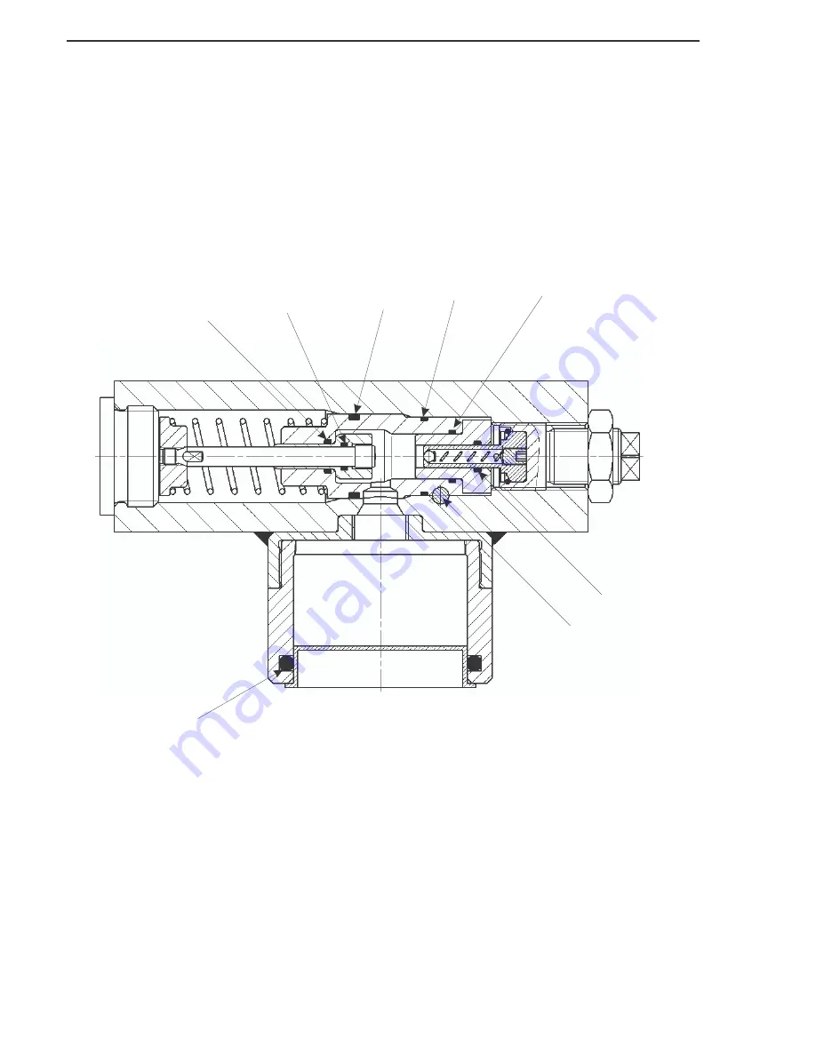
4,5

9

1

3

6

7

8

Figure 9-2. AutoLube II Seal Kit

Summary of Contents for AutoLube II

Page 1: ...AutoLube II Automated Lubrication System Construction Products Inc TECHNICAL MANUAL Manual Part No 002038 November 1 2003 ...

Page 2: ... 8 13 99 3 Art and Text 8 13 99 9 19 Text Added Hammer Models 3 15 00 3 10 11 Art 3 15 00 3 9 13 Text 3 15 00 7 19 Updated Part No s 7 19 01 throughtout Minor editting 7 19 01 19 Revised part numbers Added 797B and 805B 4 12 02 22 23 Added Seal Kit 4 12 02 10 23 02 4 16 03 11 1 03 9 10 9 10 19 9 Corrected JIC fitting sizes Corrected JIC fitting sizes Added parts information Text ...

Page 3: ... 10 5 3 MODEL 770CS INSTALLATION 11 SECTION 6 0 AUTOLUBE II OPERATION 13 6 1 THEORY OF OPERATION 13 6 2 LOADING A CARTRIDGE IN AUTOLUBE II 13 6 3 PREFILLING THE LUBRICANT LINE 13 6 4 MAINTENANCE BEFORE OPERATION 13 6 5 OPERATION 13 6 6 WORKING IN HIGH LOW TEMPERATURES 14 6 7 WORKING UNDERWATER 14 SECTION 7 0 TROUBLESHOOTING 15 7 1 AUTOLUBE II INOPERABLE 16 7 2 MANUAL LUBRICATION 16 SECTION 8 0 REM...

Page 4: ...Allied AutoLube II ii 11 1 03 This page intentionally left blank ...

Page 5: ... to the equipment if not per formed properly Read these instruc tions carefully before performing the procedure on the Allied AutoLube II Lubrication System This technical manual describes in detail the procedures needed to operate the Allied AutoLube II Lubrication System Pay care ful attention to all instructions and follow all governing regulations Operation or service other than in accordance ...

Page 6: ...Allied AutoLube II 2 11 1 03 This page intentionally left blank ...

Page 7: ...r refillable grease cartridge No tools required to change grease cartridge Self priming Adjustable output Can be used with Allied Chisel Paste Lubricant level can be monitored from operator s cab Figure 2 1 illustrates the AutoLube II main components and Figure 2 2 shows typical mounting locations of the AutoLube II on a hammer The mounting location varies with the hammer model Allied AutoLube II ...

Page 8: ...Allied AutoLube II 4 11 1 03 This page intentionally left blank ...

Page 9: ...Printing Office Superintendent of Documents P O Box 371954 Pittsburgh Pa 15250 Ask for Construction Industry OSHA Standards Stock 869 034 00107 6 3 1 OPERATOR SAFETY RECOMMENDATIONS Do not run any hydraulic lines through the operator s cab they may leak or even burst injuring the operator Relieve hydraulic oil pressure before dis connecting or removing existing lines on the carrier Collect any oil...

Page 10: ...Allied AutoLube II 6 11 1 03 This page intentionally left blank ...

Page 11: ... Line 04 BSPP Cartridge Allied Chisel Paste NOTE The use of Allied Chisel Paste will extend bushing and tool life of the hammers It is spe cially formulated with copper graphite ingredients that distinguish it from other lubricants on the market Allied Chisel Paste provides superior and longer lasting lubrication proper ties over a wide range of operating temperatures Ordering information Allied P...

Page 12: ...Allied AutoLube II 8 11 1 03 This page intentionally left blank ...

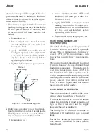
Page 13: ...and nominal inside diameter of the lubricant supply line MUST be at least 16 in 4 mm 5 1 INSTALLATION Refer to Figure 5 1 1 On models with a mounting bracket weld mounting bracket in place 2 Remove lubricating nipple from ham mer lubrication port and install adapter 1 3 Remove plug from AutoLube II hydrau lic pressure port on hammer and install adapter 2 NOTE Some Hy Ram Models have a sepa rate pr...

Page 14: ...utoLube II pump with a hand held grease gun at lubrication fit ting on pump 9 Screw Allied Chisel Paste cartridge into AutoLube II pump The cartridge can be refilled and re used 5 2 RETROFIT KIT 1 On retrofit kit installations cut hose to length and install re usable fittings not shown 2 Install 4JIC re usable fitting into el bow 7 for lubrication connection 3 Install 6JIC re usable fitting into e...

Page 15: ...nnect small hose 6 04JIC inch for hydraulic connection to AutoLube II on the bottom port of tee fitting 4 04JIC 5 Connect hose 11 04 06JIC to top port of tee fitting 4 04JIC 6 Install tee fitting 12 04BSPP 06 male JIC bottom port on Connection F two speed connection on cylinder head 7 Cap the top port of the tee fitting 12 04BSPP 06 male JIC or install two speed line 8 Install hose 11 04 06JIC on ...

Page 16: ...Allied AutoLube II 12 11 1 03 This page intentionally left blank ...

Page 17: ... bleed air from the line 1 Using a hand held grease gun prefill the lubrication lines through the lube fitting provided on the pump housing 2 To check that line is full remove the hose at the hammer hydraulic connec tion and observe that lubricant emerges from the end of the hose 6 4 MAINTENANCE BEFORE OPERATION 1 Tighten all loose fittings 2 Replace all damaged tubes or hoses 3 Check the lubrican...

Page 18: ...k nut 4 Tighten lock nut when properly set 6 6 WORKING IN HIGH LOW TEMPERATURES The AutoLube II is powered by pressurized hydraulic oil from the carrier s hydraulic system The oil temperature should never exceed 176o F 80o C in accordance with the carrier manufacturer s recommenda tions When using the Autolube II with the Allied hydraulic hammer the use of Allied Chisel Paste is recommended This p...

Page 19: ...s blocked Open branch from ham mer pressure line valve block on boom Pressure oil line to system leaks Check fittings and hose replace if necessary and tighten properly Lubricant line blocked or too long Check hose replace if necessary maximum length 15 feet Perform functional test with hose uncoupled Lubricant cartridge in stalled incorrectly Reinstall cartridge correctly refer to Section 6 2 che...

Page 20: ...lubricating nipple from AutoLube II to hammer as follows 1 Unscrew the lubricant line from the hammer connection 2 Remove lubricating nipple from the AutoLube II 3 Screw lubricating nipple directly into hammer connection 4 Lubricate using a hand held grease gun Allied AutoLube II 16 11 1 03 Problem Cause Remedy Lubricant Supply too Low Piston stroke set too short Adjust piston stroke refer to Sect...

Page 21: ...omplete AutoLube II and store in a secure place 8 2 REMOVING HOSES Unscrew the AutoLube II hoses from the hydraulic and lubrication ports on the hammer or from the check valve in the hy draulic line on retrofit kits 8 3 REATTACHING AUTOLUBE II AFTER IDLE PERIODS 1 Clean the lubricant line which is still connected to the hammer and remove any blockages formed by residual lubri cant 2 Refer to SECTI...

Page 22: ...Allied AutoLube II 18 11 1 03 This page intentionally left blank ...

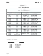
Page 23: ... Bracket 680845 770 AutoLube II Port Clamp to Box Slot 100221 775 AutoLube II Port Welded Bracket 100216 785 Large Port Flange Welded Bracket 100214 795 AutoLube II Port Welded Bracket 100214 797 AutoLube II Port Welded Bracket 100214 797B AutoLube II Port Welded Bracket 680851 805 AutoLube II Port Welded Bracket 680851 805B AutoLube II Port Welded Bracket 680856 905 Large Port Flange Welded Brack...

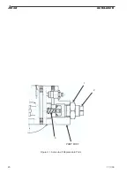
Page 24: ...Allied AutoLube II 20 11 1 03 1 2 PUMP BODY 3 Figure 9 1 AutoLube II Replaceable Parts ...

Page 25: ...e AutoLube II s listed on on page 19 These parts are shown on the opposite page Allied AutoLube II 11 1 03 21 AutoLube II Replaceable Parts ITEM NO QTY PART NO DESCRIPTION 1 1 100313 Lock Nut 2 1 100314 Adjustment Stem 3 1 660289 Check Valve w Snap Ring ...

Page 26: ...Allied AutoLube II 22 11 1 03 2 4 5 9 1 3 6 7 8 Figure 9 2 AutoLube II Seal Kit ...

Page 27: ...Seal Kit Part Number 660288 ITEM NO QTY PART NO DESCRIPTION 1 1 102243 O Ring 2 1 102244 O Ring 3 1 102245 O Ring 4 1 102246 Locking Pin Pump 5 2 102248 Expander Plug Pump 6 1 667225 O Ring 7 1 102247 O Ring 8 1 659551 O Ring 9 1 102249 O Ring ...

Page 28: ......

Reviews: