507787-01
Issue 2007
Page 2 of 22
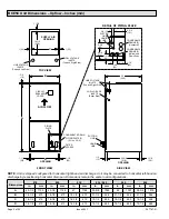
A
B
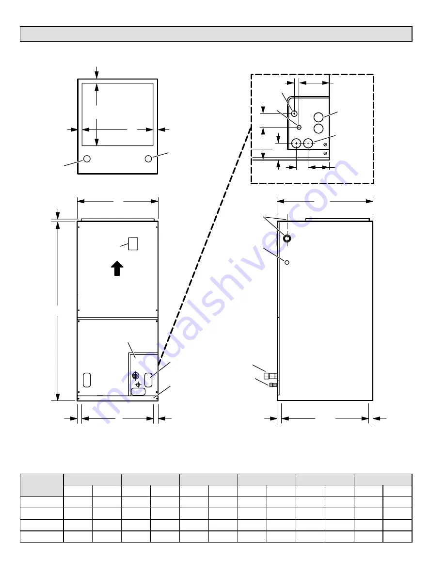
FRONT VIEW
SIDE VIEW
LINE VOLTAGE
INLETS
(Top and Right Side)
LOW VOLTAGE
INLETS
(Either Side)
SUCTION
LINE
LIQUID
LINE
FILTER
ACCESS
3/4
(19)
AIR FLOW
CIRCUIT
BREAKER
COVER
D
1-1/8
(29)
1/2
(13)
C
LINE VOLTAGE
INLETS
(Top and Left Side)
LOW VOLTAGE
INLETS
(Top and Right Side)
1 (25)
SUPPLY AIR
OPENING
TOP VIEW
OPENING
OPENING
1 (25)
1 (25)
1-1/8
(29)
1-1/8
(29)
20-3/8
(518)
22
(559)
14-1/2
(368)
DETAIL OF PIPING PLATE
LIQUID
LINE
CONDENSATE
DRAINS (2)
(Horizontal)
1-3/4
(44)
3/4 (19)
2-3/4
(70)
3-1/2
(89)
PIPING
PLATE
4-3/4
(121)
4-3/8
(111)
2-3/8
(60)
CONDENSATE
DRAINS (2)
(Upflow and
Downflow)
SUCTION
LINE
CONDENSATE DRAIN
PIPING PLATE (3)
(2-1/4 x 3-3/4)
BCE5C
Unit Dimensions – Upflow – Inches (mm)
Dimensions
018
024
030
036 / 042
048
060
in.
mm
in.
mm
in.
mm
in.
mm
in.
mm
in.
mm
A
43-1/2
1105
45-1/2
1156
47
1194
53-5/8
1362
55
1397
59-3/4
1518
B
18-1/2
470
18-1/2
470
18-1/2
470
21-1/2
546
21-1/2
546
21-1/2
546
C
16-1/2
419
16-1/2
419
16-1/2
419
19-1/2
495
19-1/2
495
19-1/2
495
D
16-1/4
413
16-1/4
413
16-1/4
413
19-1/4
489
19-1/4
489
19-1/4
489
NOTE:
Unit is shipped configured for horizontal right-hand air discharge. Unit may be converted to horizontal left-hand air
discharge by repositioning horizontal drain pan. Dimensions remain the same in all configurations.


