background image


  6.  Repeat with other bearing and  
 housing. 

  7.  Install cover plate, adapter plate 
 and 

bolts. 

  8.  Install hydraulic motor. 

~CAUTION~

Follow bolt torque specifications. Refer 
to Section 11.6. 

  9.  Install hydraulic hoses. 

10.  After completely assembled, follow 

installation and daily lubrication 
procedures.

11.8 Spring Mounts 

The spring  mounts are subject to aging 
and require periodic replacement. While 
mount life depends primarily on use, 
extreme environmental conditions and 
other factors can shorten mount life. 
  1.  Position Ho-Pac on flat, stable 

surface.

  2.  Adequately support or block the 

mounting  frame to relax mounts. 

~WARNING~

Do not place hands or fingers between 
Mounting Frame and Baseplate during 
removal of spring mounts or mount 
nuts. Injury could result. 

  3.  Loosen all nuts prior to mount 

removal.

  4.  Remove mount nuts. 

  5.  Remove mount. 

  6.  Position new mount and re-install 

nuts. See Section 11.6. 

If multiple mounts are to be replaced, it 
is recommended to completely replace 
one mount at a time. 

11.9 Hydraulic Motor 

There are no user-servicable parts in the 
hydraulic motor. Contact the Allied 
Technical Service Department for 
further information. 

11.10 Warranty Protection 

Maintain written records of Ho-Pac 
maintenance, service and repair. These 
records will be helpful if warranty 
coverage is ever in question. Each record 
shall include : 

x

The date of service, maintenance or 
repair.

x

A description of the service, 
maintenance or repair performed. 
Include part numbers if applicable. 

x

Copies of purchase order(s) and 
invoice(s) for repair parts and service. 

x

The name and signature of the 
person performing the service, 
maintenance or repair. 

27

7/21/03

Summary of Contents for Ho-Pac NT8900 Series

Page 1: ......

Page 2: ...Allied Ho Pac Model NT8900 Series Document Change Notice ...

Page 3: ...Owners Responsibilities 25 6 2 General Construction Safety 25 6 3 Federal State Local and OSHA Construction Guidelines and Regulations 25 6 4 General Safety Summary 25 6 4 1 Cautions and Warnings 25 6 4 2 Personnel Precautions 26 Section 7 0Carrier Application 27 Section 8 0 Installation Removal 28 8 1 Installation 28 8 2 Removal 29 Section 9 0 Operation 30 Section 10 0 Troubleshooting 32 Section ...

Page 4: ...Section 12 0 Lifting Transport 37 12 1 Lifting Transporting Off Carrier 37 12 2 Lifting Transporting On Carrier 37 Section 13 0 Storage 38 Section 14 0 Parts Information 39 7 21 03 ii ...

Page 5: ...idelines Pay particular attention to WARNINGS and CAUTIONS identified with this symbol These instructions are important for personnel safety and full service life of the Ho Pac Follow them carefully 1 2 Warranty Information Warranty coverage of the Allied Ho Pac depends on proper maintenance and operation of the Ho Pac as detailed in this manual Improper maintenance or operation shall void Ho Pac ...

Page 6: ... service consistent with industry practices Allied takes no responsibility for the results of actions not recommended in this manual and specifically the results of x Operation in non recommended applications x Incorrect operation x Improper maintenance x Use of service parts not approved or supplied by Allied These exclusions apply to damage to the Ho Pac associated equipment and injury to person...

Page 7: ...s to densities of 95 Proctor Soils with moisture contents near their maximum density improve compaction effective ness The Allied Ho Pac vibrational compactor consists of the following major subassemblies The DYNAMIC ASSEMBLY includes the hydraulic motor bearings eccentric mass housing frame and base plate This assembly generates and transfers the vibratory energy to the soil The SUSPENSION SYSTEM...

Page 8: ...r boom The weight of the Ho Pac and the boom plus the high impulse vibration forces produced by the Ho Pac are ideal for compacting granular materials The vibrations generate stress waves which bring the air in the soil to the surface the soil particles are compressed and compacted These same forces can also effectively compact cohesive materials Optimum compaction is usually obtained with two pas...

Page 9: ...draulic Flow Pressure Recommended Flow Max Opr Pres Motor Options gpm lpm psi bar 12 45 2800 193 18 68 2000 138 21 79 2000 138 Operating Pressure No Load 300 500 psi 21 34 bar Hydraulic Capacity 0 3 gal 1 21 Approximate Base Plate 16 x 32 41 cm x 81 cm Compaction Area 4 7 ft2 0 43 M2 Hydraulic Hose Size Pressure Line inch diameter 19 mm Return Line inch diameter 19 mm Recommended Carrier Weight Ba...

Page 10: ... Weight lbs kg 830 377 920 417 900 408 Height In mm 36 916 28 708 32 814 Width In mm 16 406 16 406 16 406 Depth In mm 39 990 38 965 39 990 Mounting Pin Diameter in mm Varies Mounting Bracket Required Mounting Bracket Required Max Boom Width In mm 10 1 257 Varies Varies 7 21 03 6 ...

Page 11: ...NSION DIAGRAMS VMS V10 Dimension Diagram 7 30 185 42 16 00 406 40 10 63 269 88 36 05 915 80 11 25 285 75 17 25 438 15 38 78 985 01 19 00 482 60 8 00 203 20 32 00 812 80 36 00 914 40 Center of Gravity 7 7 21 03 ...

Page 12: ...Custom Flat Top Dimension Diagram 32 00 812 80 36 00 914 40 16 00 406 40 37 97 964 53 32 05 814 20 17 00 431 75 21 75 552 45 8 00 203 20 Center of Gravity Center of Gravity 7 21 03 8 ...

Page 13: ...BCS Dimension Diagram 32 00 812 80 36 00 914 40 27 86 707 66 16 00 406 40 10 62 269 87 3 15 80 01 6 30 160 02 13 39 340 00 8 00 203 20 Center of Gravity 9 7 21 03 ...

Page 14: ...in a safe distance from the Ho Pac during operation The READ INSTRUCTION decal indicates that it is important for the operator to read them all prior to transporting installing operating or servicing the Ho Pac The HOT SURFACE decal indicates that the hydraulic components may be hot and that proper protective equipment is required These components include the valve quick disconnect couplings hoses...

Page 15: ...4 4 DECAL LIFTING AND LUBRICATION DIAGRAMS VMS V10 Ho Pac Decal and Lubrication Drawing 4 2 1 2 7 5 3 5 4 7 2 2 6 8 8 3 1 2 7 2 5 4 3 5 2 7 2 4 8 8 6 3 1 2 7 2 5 4 3 5 2 7 2 4 8 8 6 3 11 7 21 03 ...

Page 16: ...o Description 1 1 676980 ID Plate 2 4 676982 Lift Point 3 2 676985 Grease 8 hr 4 2 676981 Stay Clear 5 2 676984 Read Instructions 6 1 676983 Hot Surface 7 2 676653 Allied Logo 8 2 102210 Decal Model NT8900 9 1 818676 Pressure ID Tag Located on Pressure Hose 7 21 03 12 ...

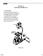
Page 17: ...s as shown in the diagram below The combination of the VMS design frame and a VMS mounting kit provides unequaled versatility and ease in attaching the units to carriers and in transferring a Ho Pac from one carrier to another Also Ho Pacs can be quickly adapted to different quick couplers VMS Mounting 13 7 21 03 ...

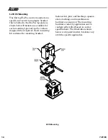
Page 18: ...d can be custom designed when required Each mounting kit contains the mounting bracket fastener kit pins and bushings spacers sleeve bushings and miscellaneous hardware as required The mounting hardware varies by application and is configured by Allied based on carrier specifications The illustration shown below is a typical bracket brackets vary with the specific application BCS Mounting 7 21 03 ...

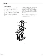
Page 19: ...y good for compaction in trenches or whenever the area of operation is not in line with the stick The bottom of the swivel mount attaches to the Ho Pac frame with mounting pins and related hardware or to the flat top with a fastener kit The top of the swivel mount is attached to the carrier For more detailed swivel information contact Allied Construction Products or an Allied distributor Swivel Mo...

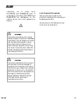
Page 20: ...ted States comply with the recommendations of the Occupational Safety and Health Administration standards of the U S Department of Labor For OSHA construction guidelines contact your local federal government office or write U S Government Printing Office Superintendent of Documents P O Box 371954 Pittsburgh Pa 15250 Ask for Construction Industry OSHA Standards Stock 869 034 00107 6 6 4 General Saf...

Page 21: ...injury Read this manual thoroughly before operating or maintaining the Ho Pac CAUTION Instructions identified with this symbol are important to prevent damage to equipment and to maintain full service life of the Ho pac Follow them carefully Operation or service not in accordance with these instructions may subject the Hole Hog to conditions beyond its design capability Read this manual thoroughly...

Page 22: ...C series valves The AC series solenoid operated valve provides regulated priority flow at a controlled pressure Always follow hydraulic kit installation instructions Carrier hydraulic circuit designs differ and damage to the Ho Pac or carrier may result if the hydraulic kit is improperly installed Contact Allied for installation recommendations While the Ho Pac is designed to minimize the vibratio...

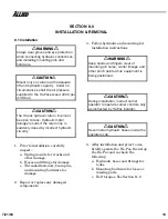
Page 23: ...nd other damage b Hoses and fittings for damage c Threaded fasteners boom pins and mounting hardware for damage 2 Repair or replace any damaged components 3 Follow hydraulic and mounting kit installation instructions WARNING Keep hands and fingers clear of mounting pin holes carrier linkage and other pinch points while equipment is being positioned CAUTION During installation instruct carrier oper...

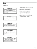
Page 24: ...ion WARNING Keep hands and fingers clear of mounting pin holes carrier linkage and other pinch points while equipment is positioned CAUTION During removal instruct carrier operator to operate carrier controls only as instructed by Ho Pac installer 1 Position Ho Pac safely on the ground 2 Remove hydraulic connections 3 Be sure unit is stable prior to removing mounting hardware 4 Remove mounting har...

Page 25: ... to operation 3 Daily lubricate bearings See Section 11 5 4 Prior to compaction the excavation shall be back filled using other equip ment CAUTION Do not use the Ho Pac to move materials Ho Pac damage may result 5 Position carrier in line with direction of work 6 Position the Ho Pac base plate parallel to the work surface and within view of the operator The base plate must be in full contact with ...

Page 26: ...wn force with the carrier For larger areas a repetitive back and forth sweeping motion is effective Continue the initial pass until compaction is no longer apparent typically 10 to 15 seconds 10 It may be necessary to adjust the idle speed of the carrier to maintain proper Ho Pac flow requirements CAUTION Do not operate Ho Pac with hydraulic oil temperature above 180o F 82o C or pressures above 22...

Page 27: ...sure or flow Check hydraulic supply system Correct as required b Failed spring mount Inspect and replace failed mount 3 Unit runs with excessive noise or vibration a Loose bolts or mounting hardware Inspect and tighten bolts b Failed bearing Inspect and replace bearings 4 Unit runs but stalls under load a Pressure relief too low Check hydraulic supply system Correct as required b Failed bearing In...

Page 28: ...n safe work areas Never service the Ho Pac on the carrier or in the trench Maintain clean oil Follow the carrier manufacturer s recommendations for hydraulic oil grade and hydraulic system maintenance Clean and properly dispose of any spilled oil as required by governing regulations Contact the Allied Technical Service Department with questions regarding maintenance operation or replacement parts ...

Page 29: ...impurities from the bearings to increase bearing life Recommended grease Use a premium quality multipurpose extreme pressure petroleum based grease with lithium and anti rust additives Minimum oil viscosity shall be 14 5 cSt at 100o C Approved brands Shell Oil Alvania EP2 Mobile Oil Co Mobilux EP2 Texaco Inc RB2 1 Position Ho Pac for easy access to lubrication fittings 2 Carefully clean lubricatio...

Page 30: ...rbor press is recommended Do not attempt to replace bearings in the field CAUTION Use only Allied replacement parts Removal 1 Remove hydraulic hoses from motor 2 Remove the cover plate hydraulic motor and adapter plate 3 Remove bearing housing assembly from the main housing It is not necessary to remove eccentric from main housing WARNING Be careful that eccentric shaft does not fall and injure ha...

Page 31: ...ount nuts Injury could result 3 Loosen all nuts prior to mount removal 4 Remove mount nuts 5 Remove mount 6 Position new mount and re install nuts See Section 11 6 If multiple mounts are to be replaced it is recommended to completely replace one mount at a time 11 9 Hydraulic Motor There are no user servicable parts in the hydraulic motor Contact the Allied Technical Service Department for further...

Page 32: ...ip ment See diagram in Section 4 4 WARNING Do not lift Ho Pac by the mounting pins The Ho Pac may shift and cause damage or injury to personnel 6 Adequately stabilize and secure Ho Pac for transport 12 2 Lifting Transporting On Carrier If the Ho Pac is transported while installed on the carrier 1 Remove all loose debris from Ho Pac 2 If the swivel assembly is installed lock swivel position with bo...

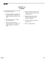
Page 33: ...ecure hoses to unit to prevent accidental damage 3 Protect spring mounts and hydraulic hoses from weather and direct sunlight to reduce aging effects 4 Support the Mounting Frame with blocks to minimize permanent sag in spring mounts 5 Keep the motor full of oil and lubricate bearings to protect internal components 6 Avoid wet or damp conditions to minimize rust 7 Store in upright position 29 7 21...

Page 34: ...This Page Intentionally Left Blank 7 21 03 30 ...

Page 35: ...SECTION 14 0 PARTS INFORMATION NOTE The following illustrations and parts lists are typical models of the NT8900C Ho Pac Specific assemblies and mounting configurations may vary 31 7 21 03 ...

Page 36: ...Dynamic Assembly and Suspension System 8 7 6 5 4 2 1 12 10 2 11 2 9 6 5 13 2 1 15 2 17 16 3 20 18 19 18 14 7 21 03 32 ...

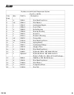
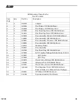
Page 37: ...101814 Eccentric Housing 9 32 708787 Torque Nut 10 32 719730 Hex Head Cap Screw 11 4 719749 Spring Mount 12 1 708717 Lubrication Fitting 13 1 708779 Adapter Plate 14 4 719101 Hex Head Cap Screw 15 1 102867 Hydraulic Motor S N 8049 Below 15 1 Optional Hydraulic Motor S N 8850 Above Refer to Table 14 1 Motor Valve Packages 16 2 656531 90q Elbow S N 8849 Below 17 2 708791 Hex Head Cap Screw 18 8 7190...

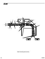
Page 38: ...8 1 2 3 16 7 13 14 15 14 11 6 5 9 10 12 5 4 VMS V10 Mounting Frame Ho Pac 7 21 03 34 ...

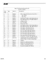
Page 39: ...Hex Head Cap Screw S N 8850 Above 10 2 865384 Flat Washer S N 8849 Below 10 2 653339 Flat Washer S N 8850 Above 11 1 678931 Hose Assembly S N 8849 Below 11 1 102865 Hose Assembly S N 8850 Above 12 1 678930 Hose Assembly S N 8849 Below 12 1 102865 Hose Assembly S N 8850 Above 13 1 676721 Check Valve X Line S N 8849 Below 13 1 Optional Flow Regulator Valve S N 8850 Above Refer to Table 14 1 Motor Va...

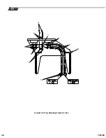
Page 40: ...5 8 9 2 7 10 6 Custom Flat Top Mounting Frame Ho Pac 7 21 03 36 ...

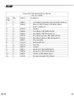
Page 41: ...pter 3 2 865384 Flat Washer S N 8849 Below 3 2 653339 Flat Washer S N 8850 Above 4 2 676799 Hex Head Cap Screw S N 8849 Below 4 2 813290 Hex Head CapScrew S N 8850 Above 5 2 659007 Hose Assembly 6 1 101834 Mounting Frame 7 2 101280 Hex Cap 8 2 656723 Adapter 9 2 883671 Elastic Nut S N 8849 Below 9 2 759808 Elastic Nut S N 8850 Above 10 2 656531 90º Elbow S N 8850 Above 11 1 101798 Dynamic Assembly...

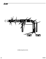
Page 42: ...5 4 1 1 7 14 6 3 2 11 10 15 8 12 8 13 9 BCS Mounting Frame Ho Pac 7 21 03 38 ...

Page 43: ...bly Pressure S N 8849 Below 5 1 102865 Hose Assembly S N 8850 Above 6 1 102110 Mounting Frame 7 2 659007 Hose Assembly 8 2 667566 Hex Head Plug S N 8849 Below 9 1 670006 Q D Coupling Package Includes Items 10 11 10 1 670007 Q D Socket 11 1 670008 Q D Plug 12 1 670270 Check Valve 5000 psi S N 8849 Above 13 1 708726 Adapter w Port S N 8849 Below 14 1 676721 Check Valve X Line S N 8849 Below 14 1 opt...

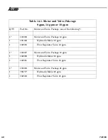
Page 44: ...otor and Valve Package 12 gpm 1 101346 Hydraulic Motor 12 gpm 1 102650 Flow Regulator Valve 12 gpm 1 103007 Motor and Valve Package 18 gpm 1 102668 Hydraulic Motor 18 gpm 1 102651 Flow Regulator Valve 18 gpm 1 103008 Motor and Valve Package 21 gpm 1 708777 Hydraulic Motor 21 gpm 1 102652 Flow Regulator Valve 21 gpm 7 21 03 40 ...

Page 45: ...This Page Intentionally Left Blank 41 7 21 03 ...

Page 46: ......

Reviews: