background image

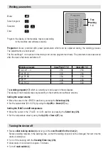
Menu


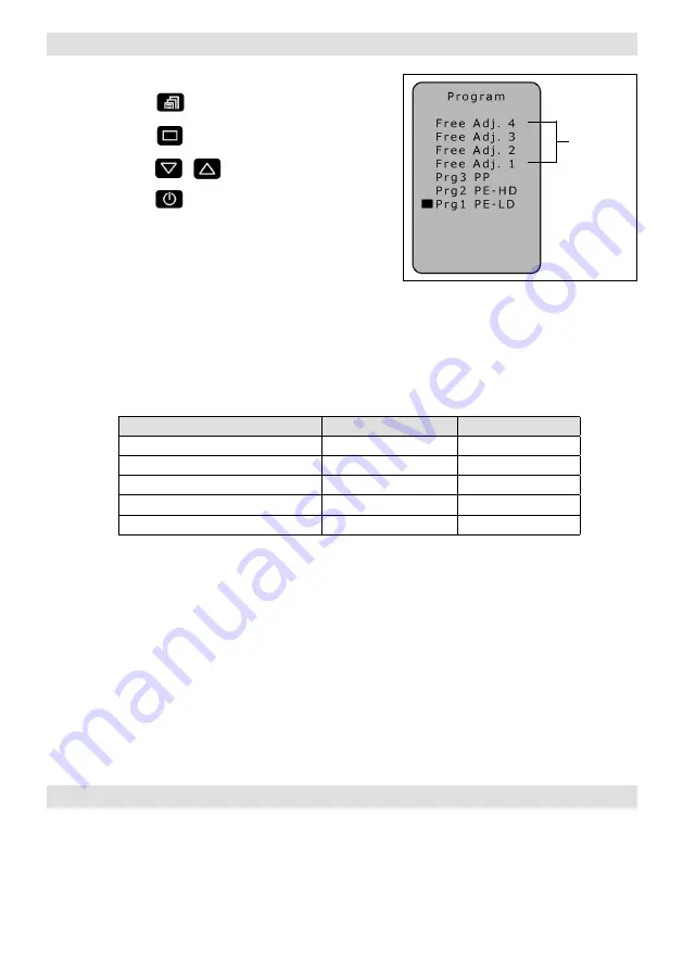
Select program 

Selection

Enter

Programs 1-3

 are provided with preset parameters which can be adjusted during the welding process. 

The adjustments are not saved!
The free settings 1-4 are preset in the factory and can be programmed freely. The parameters are saved even 
after the device has been switched off.

Setting the output volume

• Move the cursor to the «SPEED» position by pressing the 

Select key (28).

• Set the output value (30-100 %) by using the 

Up (29)

 or 

Down (27)

 key.

Setting the PLAST and AIR temperature

• Move the cursor to the «PLAST» or «AIR» position by pressing the 

Select key (28).

• Set the temperature value by using the 

Up (29)

 or 

Down (27)

 key.

The 

welding program (17)

 which is currently set can be seen in the workspace. 

The display of the materials may vary according to the machine and software versions.

Free 

setting 

1-4

 Welding program  

Ideal PLAST [°C]

Ideal AIR [°C]

 Free set 1 – 4

230

260

 Prg1 PE-LD

220 

260

 Prg2 PE-HD

230

260

 Prg3 PP 

240

260

 Prg0 PVC-U

200

300

Program:  the display of the materials may vary according 

to the machine and software versions.

Welding parameters

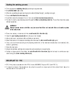
•   Release 

drive locking device (4)

 and let go of the 

on/off switch for the drive (2)

Remove welding material in the welding shoe, so that the welding shoe will not be damaged the next time the
device is started up.

• Turn off the heating with the 

Standby/Enter key (26).

• Allow device to cool down for approx. 5 minutes.
• Turn off 

main switch (1).

Turning the device off

Summary of Contents for LEISTER WELDPLAST S2

Page 1: ...WELDPLAST S2 S2 PVC S2 TPO ...

Page 2: ...check the power cord the plug and the extension cable for electrical and mechanical damage The extruder may only be opened by instructed qualified personnel Danger of fire and explosion if the hand extruder is used incorrectly e g overheating of material particularly near combustible materials and explosive gases Danger can cause burns Do not touch bare metal parts and emerging material while hot ...

Page 3: ...0 EN 55014 1 EN 55014 2 EN 61000 6 2 EN 61000 3 2 EN 61000 3 3 EN 62233 EN 60335 1 EN 60335 2 45 EN IEC 63000 Kaegiswil 03 31 2021 Bruno von Wyl CTO Christoph Baumgartner GM Disposal Do not dispose of electrical equipment with household refuse Electrical appliances accessories and packaging should be recycled in an environmentally friendly manner When you are disposing of our products please obser...

Page 4: ...value air 22 Drive display bars 23 Output display 24 Menu key 25 Back key 26 Standby Enter key 27 Down key 28 Select key 29 Up key 30 Drive status display 31 Cursor With external air duct 24 27 28 29 30 31 17 18 19 20 21 22 23 25 26 With integrated air duct 10 Pipe clip 11 Protection tube 12 Filler rod insertion point 13 Device grip 14 Power supply cord 15 Heating element protection tube 16 Hot ai...

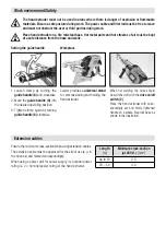
Page 5: ...s and hot streams of air must be kept at a safe distance from the base and walls 1 Loosen clamp by turning the guide handle 6 anti clockwise 2 Move the guide handle 6 into the desired operating position 3 Tighten clamp again by turning guide handle 6 clockwise Leister provides a universal stand for commissioning and holding the hand extruder Setting the guide handle Workplace Ensure the minimum cr...

Page 6: ...The hand extruder takes around 6 minutes to reach its temperature range If the power is only turned off for a short time the start up process does not need to be repeated Motor disabled Start up waiting period 220 seconds Heating M free Ready Drive status display 30 Heating until ideal values are reached Motor release Ready to weld The temperature control prevents the hand extruder from being star...

Page 7: ...volume The output volume and the pre heating time can be coordinated with each other according to the type of seam Presetting on the display Move the cursor to the SPEED position by pressing the Select key 28 Specify the maximum output value 30 100 using the Up 29 or Down 27 keys displayed on the drive display bars 22 Precise adjustment during the welding process The output volume can be reduced f...

Page 8: ...f switch for the drive 2 Direct the pre heating nozzle 9 onto the area to be welded Warm the area to be welded with oscillating movements Attach the device to the prepared welding area and press the drive on off switch 2 again Carry out a test weld according to the welding instruction of the material manufacturer and national stan dards or guidelines Check the test weld Adjust temperature settings...

Page 9: ...y using the Up 29 or Down 27 key The welding program 17 which is currently set can be seen in the workspace The display of the materials may vary according to the machine and software versions Free setting 1 4 Welding program Ideal PLAST C Ideal AIR C Free set 1 4 230 260 Prg1 PE LD 220 260 Prg2 PE HD 230 260 Prg3 PP 240 260 Prg0 PVC U 200 300 Program the display of the materials may vary accordin...

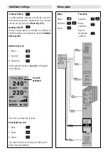
Page 10: ...f using the Standby Enter key 26 Menu Menu Selection Select Functions Selection Select and Back Back to workspace selection Activate key lock 1 Menu 2 Key lock 3 Activating If the keypad is locked key lock will appear in the display The lock is released as follows Deactivate key lock 1 Back 2 Reset 3 Select The reset must be confirmed by pressing the Select key immediately Key lock activated Addit...

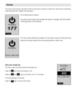
Page 11: ...ch standby on or off Press the and keys to set the time from 5 120 minutes The factory setting is 40 minutes Press the key to return to Work mode The cooling process is initiated If any key is pressed before the countdown has elapsed in standby mode 180 seconds the display returns to the initial state If no key is pressed during the countdown the cool down mode starts Pressing any key heats up the...

Page 12: ...nternal protection against excessive temperatures will turn the drive off see Err04 Accidental start up protection for the drive The drive motor is protected against accidental start up after errors e g overheating Err04 The message Switch off drive appears in the display 5 while the drive motor is disabled After correcting the error and switching off the drive release drive locking device 4 and l...

Page 13: ...properly with the clamp screws 35 Danger can cause burns Only work with heat resistant gloves The welding shoe must be changed while the device is still warm from operation 8 Welding shoe 32 Extruder nozzle 33 Fastening screw 34 Welding shoe holder 35 Clamp screw The welding shoe 8 can be turned infinitely to the desired welding direction by loosening the clamp screws 35 The clamp screws 35 must b...

Page 14: ... Seam width to 15 mm Nozzle 2 Seam width 16 to 20 mm Nozzle 3 Seam width 21 to 40 mm Pre heating nozzles for extruders with external air duct Changing the pre heating nozzle 9 44 43 Leister Technologies AG offers the right welding shoes for all common types of seam in various sizes Blank V Seam Fillet weld Overlap seam Corner seam outside Corner seam short Corner seam long Angled adapter WELDPLAST...

Page 15: ...ozzle 32 of welding residue every time the welding shoe is changed Service and Repairs Warranty For this tool the guarantee or warranty rights granted by the relevant distributor seller shall apply In case of guarantee or warranty claims any manufacturing or workmanship defects will either be repaired or replaced by the distributor at its discretion Warranty or guarantee rights have to be verified...

Page 16: ...Your authorised Service Centre is Copyright by Leister Allied Power Tools 12 76 Rushdale St Knoxfield VIC 3180 Australia T 61 3 9764 2911 E sales alliedpowertools com au W www alliedpowertools com au ...

Reviews: