14
Fixture Attachment
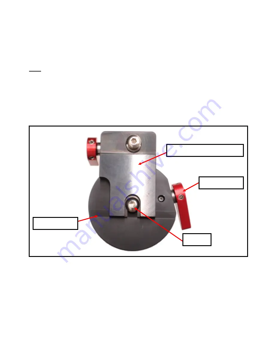
All fixtures are mounted to the bottom plate of the micro-hub assembly at the bottom of the
spindle. Each fixture has a common U-shaped cutout. The flat edge of the fixture is positioned
against the reference edge located behind the cam-lock plunger (Figure 8).
Note:
The spindle should be raised using the vertical adjustment knob so the sample and fixture
fit without contacting the platen/abrasive.
To attach a fixture, slide it onto the plate until it makes full contact with the reference edge. Make
sure it has engaged the cam-lock plunger. Rotate the cam-lock lever clockwise until tight.
Mounting the sample onto the fixture is usually done with hot mounting wax, double-sided
adhesive tape, glue, or set-screws, as required by the type of sample and desired sample
orientation.
Figure 8:
Bottom view of a fixture attached to the Micro-Hub Assembly
Reference Edge
Plunger
Cam-Lock Lever
Cam-Lock Adapter, #15-1005
Summary of Contents for MultiPrep System 15-2000-GI
Page 35: ...35 MultiPrep System Wiring Diagrams ...
Page 36: ...36 ...
Page 37: ...37 ...
Page 38: ...38 ...
Page 39: ...39 CE Certificates ...
Page 40: ...40 ...
Page 41: ...41 ...
Page 42: ...42 This page has been left blank intentionally ...
Page 43: ...43 This page has been left blank intentionally ...


