CAL (I) (J)
The calibrator circuit is crystal controlled and supplies 2 calibration frequencies. By pushing
knob (I) to it's "in" position you activate the 25 kHz calibrator, which will provide marker signals
every 25 KHz from 3.5 to 30.0 MHz. By pushing knob (J) to it's "in" position you activate the
100 KHz calibrator, which will provide marker signals every 100 KHz from 3.5 to 30.00 MHz.
RF Gain (L) AF Gain (K)
These are concentric controls.
(L) This is the receiver sensitivity control. For ordinary reception it should be set at maxi-
mum (extreme clockwise position). It should be adjusted only in such cases where an ex-
tremely strong signal from a local station may overload the receiver, causing distortion
and a resultant decrease in sound level.
(K) This is the volume control. Turn to the right in a clockwise direction to increase vol-
ume, and to the left to decrease volume.
S-Meter Readings (M)
The S-Meter provides a means of measuring the relative strength of incoming signals. Relative
readings are only correct when the RF-GAIN control is fully clockwise. Measurements are read
in "S" units from 1 to 9 and in decibels above S-9 from 0 to 40 dB.
Q Multiplier (N) (O)
(N)
Q multiplier selector switch, determines rejection or selection mode.
(O)
Tune control, moves the notch or peak thru the passband.
Phones (P)
The Phones jack (J7) provides audio output from the final audio stage. The Phones Jack has an
output impedance of 8 ohms. When using the Phones Jack the speaker jack is disabled.
- 10-
Summary of Contents for SX-190
Page 1: ......
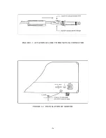
Page 7: ...FIGURE 1 3 ATTACHING CABLE TO PHONE PLUG CONNECTOR FIGURE 1 4 INSTALLATION OF GROUND 6 ...
Page 17: ... 16 ...
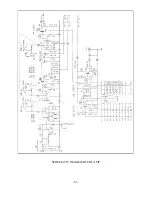
Page 22: ...SCHEMATIC DIAGRAM OF RF AMP 21 ...
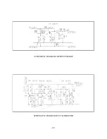
Page 23: ...SCHEMATIC DIAGRAM OF BUFFER AMP SCHEMATIC DIAGRAM OF CALIBRATOR 22 ...
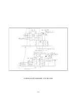
Page 24: ...SCHEMATIC DIAGRAM OF VFO SECTION 23 ...
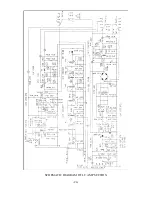
Page 25: ...SCHEMATIC DIAGRAM OF I F AMP SECTION 24 ...
Page 26: ...SCHEMATIC DIAGRAM OF POWER SUPPLY 25 ...
Page 29: ......
Page 30: ......
Page 31: ......

