OPERATING INSTRUCTIONS
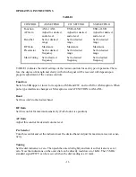
TABLE 1
CONTROL
AM SETTING
CW SETTING
SSB SETTING
Function
AM or ANL
USB or LSB
USB or LSB
AF Gain
Adjust for desired
audio level
Adjust for desired
audio level
Adjust for desired
audio level
Band Sel
Set for desired
range
Set for desired
range
Set for desired
range
RF Gain
Maximum
Maximum
Maximum
Preselector Set
for
desired
frequency
Set for desired
range
Set for desired
range
Main Tuning
Set to desired
frequency
Set to desired
frequency
Set to desired
frequency
TABLE 1 indicates the initial settings of the various controls for each type of operation. There-
fore, the degree of strength and clarity with which signal will be received will depend upon
proper readjustment of the various controls.
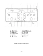
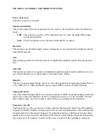
Function
Switch to SSB upper or lower for reception of SSB and CW. and to AM for AM reception. When
pulse type interference hampers AM reception, switch FUNCTION to AM-ANL.
Band
Set this switch to the desired band.
RF Gain
Set this control for maximum sensitivity (Full clock-wise position).
AF Gain
Adjust this control for desired volume level.
Pre Selector
Turn this control and set the indicator near the desired band. Adjust for maximum receiver sensi-
tivity.
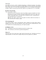
Tuning
Set the dial indicator to zero. Then push the outer dial lightly and turn it so that it also is set at
zero. Now the indications on the outer dial can be directly read down to 1 KHz. The 15 MHz
standard signal WWV can be received when the dial reading is at 0 mark.
-11-
Summary of Contents for SX-190
Page 1: ......
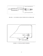
Page 7: ...FIGURE 1 3 ATTACHING CABLE TO PHONE PLUG CONNECTOR FIGURE 1 4 INSTALLATION OF GROUND 6 ...
Page 17: ... 16 ...
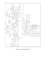
Page 22: ...SCHEMATIC DIAGRAM OF RF AMP 21 ...
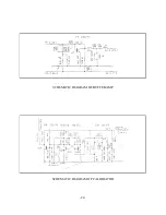
Page 23: ...SCHEMATIC DIAGRAM OF BUFFER AMP SCHEMATIC DIAGRAM OF CALIBRATOR 22 ...
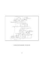
Page 24: ...SCHEMATIC DIAGRAM OF VFO SECTION 23 ...
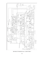
Page 25: ...SCHEMATIC DIAGRAM OF I F AMP SECTION 24 ...
Page 26: ...SCHEMATIC DIAGRAM OF POWER SUPPLY 25 ...
Page 29: ......
Page 30: ......
Page 31: ......

