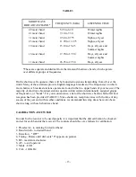
TABLE 3
SHORTWAVE
BROADCAST BAND*
FREQUENCY (MHz)
LISTENING TIME
49 meter band
5.95 to 6.20
Winter nights
41 meter band
7.10 to 7.30
Winter nights
31 meter band
9.50 to 9.775
Nights, all year
25 meter band
11.70 to 11.975
Nights, all year
19 meter band
15.10 to 15.45
Days, all year and
Summer
nights
16 meter band
17.70 to 17.90
Days, all year and
Summer
nights
11 meter band
26.95 to 27.50
Days, all year
*These are separate and distinct from the Amateur Shortwave bands, which operate
over different groups of frequencies.
On the short wave frequencies there will be found radio stations transmitting from all over the
world. Many of these stations provide English-language broadcasts. The frequencies on which
most shortwave broadcast stations operate are found in the two upper bands of your receiver. The
majority of shortwave broadcast stations operate within certain internationally assigned groups
of frequencies, or "bands". For your convenience, a list of the shortwave bands which offer best
reception has been provided (TABLE 3). Since shortwave reception varies with the time of day,
season of the year and with weather conditions, recommended listening times have also been
shown along with each shortwave band.
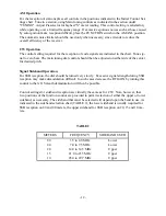
CALIBRATION AM/CW/SSB
In order for the receiver to be used properly it is important that the dial calibration be checked
and set for each band of the receiver. The controls should be set as follows for calibration:
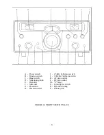
1. Preselector - to marking for desired band
2. Band switch - to desired band
3. Rejection - "OFF"
4. Tuning - Rotate until dial scale "0" appears on pointer.
5. RF - maximum clockwise
6. AF - to suit operator
7. Mode - LSB
8. CAL - 100 KHz.
- 13-
Summary of Contents for SX-190
Page 1: ......
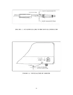
Page 7: ...FIGURE 1 3 ATTACHING CABLE TO PHONE PLUG CONNECTOR FIGURE 1 4 INSTALLATION OF GROUND 6 ...
Page 17: ... 16 ...
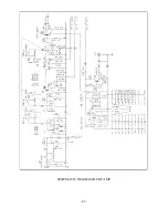
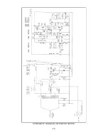
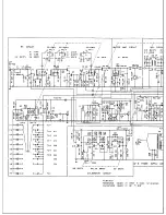
Page 22: ...SCHEMATIC DIAGRAM OF RF AMP 21 ...
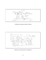
Page 23: ...SCHEMATIC DIAGRAM OF BUFFER AMP SCHEMATIC DIAGRAM OF CALIBRATOR 22 ...
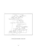
Page 24: ...SCHEMATIC DIAGRAM OF VFO SECTION 23 ...
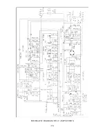
Page 25: ...SCHEMATIC DIAGRAM OF I F AMP SECTION 24 ...
Page 26: ...SCHEMATIC DIAGRAM OF POWER SUPPLY 25 ...
Page 29: ......
Page 30: ......
Page 31: ......

