GENERAL DESCRIPTION
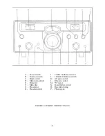
The SX-190 SHORTWAVE RECEIVER is fully transistorized and offers a new high in reliabil-
ity, selectivity, and drift free operation. It covers the 49 thru 16-meter international broadcasting
bands plus the 11-meter CB band and WWV at 10 and 15 MHz. Two blank positions are left for
the owner who may by the addition of the proper crystal, cover any 500 KHz wide segment of
frequency between 3.5 thru 10 MHz and 10.0 thru 30.0 MHz. These bands are selectable with the
front panel band selector switch.
Its circuitry uses 4 FETS, 22 transistors, 13 diodes, 2 thermistors and 2 zener regulators. Dual
conversion and mechanical filters enhance the excellent image and spurious rejection plus sharp
selectivity of this receiver.
The suppression of unwanted heterodynes and interfering carriers is enhanced by the Q-
MULTIPLIER, which provides better than 40 dB of attenuation.
The use of a PRESELECTOR assures maximum sensitivity and a high signal to noise ratio for
outstanding reception of weak signals. The tuning dial features anti-backlash construction. It is
direct reading to 1 KHz. Precise tuning of all signals including SSB is assured by the large easy
to read dial. Superior stability is obtained by the use of a crystal controlled 1st local oscillator
and a VFO 2nd oscillator. A dual frequency calibrator (25 and 100 KHz), crystal controlled, is
used for calibrating the dial readout to an accuracy of better than ±200Hz.
The SX-190 is equipped with a crystal controlled Beat Frequency Oscillator (BFO) for the recep-
tion of USB, LSB and CW signals.
Incorporated in its circuitry are AGC, ANL and S-meter functions. The AGC (Automatic Gain
Control) has been tailored to produce minimum audio output changes even with large variations
of input signal levels. ANL (Automatic Noise Limiter) operation is achieved through the use of a
diode. When pulse type interference accompanies an incoming signal, the diode in the ANL cir-
cuit operates in a cutoff mode for very brief time intervals, thus it effectively acts as a gate to
shut out undesirable noise peaks. The S-METER indicates incoming signal strength and also acts
as a tuning aid by indicating peak signal.
A dual power supply operates from a source of 110-120 volts 60 Hz AC or 12 volts DC. On AC,
a 1-ampere fuse in the secondary of the power transformer is used for protection of the equip-
ment. The B+ power supply uses a full wave rectifier and a stabilized regulator.
The antenna input is designed to operate with a wide variety of 50-75 ohm antennas. Both
speaker and headphone jacks are provided (8 ohm). For use with a companion transmitter, mut-
ing connections are available at the rear panel along with both HFO and VFO outputs.
Rugged mechanical construction plus modularized design provide for maximum mechanical sta-
bility and ready access to either the top or bottom of the SX-190. This allows for maximum ease
of maintenance or alignment should either become necessary.
-2-
Summary of Contents for SX-190
Page 1: ......
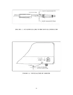
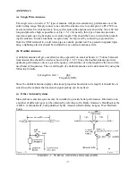
Page 7: ...FIGURE 1 3 ATTACHING CABLE TO PHONE PLUG CONNECTOR FIGURE 1 4 INSTALLATION OF GROUND 6 ...
Page 17: ... 16 ...
Page 22: ...SCHEMATIC DIAGRAM OF RF AMP 21 ...
Page 23: ...SCHEMATIC DIAGRAM OF BUFFER AMP SCHEMATIC DIAGRAM OF CALIBRATOR 22 ...
Page 24: ...SCHEMATIC DIAGRAM OF VFO SECTION 23 ...
Page 25: ...SCHEMATIC DIAGRAM OF I F AMP SECTION 24 ...
Page 26: ...SCHEMATIC DIAGRAM OF POWER SUPPLY 25 ...
Page 29: ......
Page 30: ......
Page 31: ......

