SECTION 1: INSTALLATION
1.1 UNPACKING
Immediately after receipt of the receiver it should be removed from the shipping carton and visu-
ally inspected to insure that it has not been damaged in shipment. If it is determined that the re-
ceiver has been damaged in transit the shipping carton and packing material should be saved and
the transportation company notified immediately.
As part of the initial inspection, all of the front panel controls should be checked to insure their
proper mechanical operation. It is advisable to generally, look the receiver over and verify that
nothing has been shaken loose and that everything appears to be normal.
The following items are supplied with each receiver:
1. Instruction manual, ALLIED MODEL SX-190.
2. DC power cable assembly.
3. 1/4" phone plug connector.
4. Additional feet.
1.2
RECEIVER CONNECTIONS
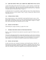
If the SX-190 Receiver is to be used for receiving only and not as part of a system with intercon-
nections to an associated transmitter there are only a few required connections. These connec-
tions are easily accessible at the rear of the receiver and their design permits permanent connec-
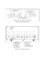
tions to be made in a neat manner. Figure 1-2 (page 5) illustrates the connections points at the
rear of the receiver.
1.2.1 ANTENNA CONNECTION
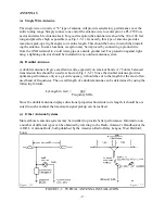
The SX-190 Receiver has been designed to operate from a 50-75 ohm unbalanced antenna input.
To obtain the best results from the receiver the antenna that most nearly suits your needs should
be selected. The illustrations shown in Figure 1-5 (page 7) are typical antenna installations. All
that is required is to install a PL-259 connector on the feed line and connect it to the antenna in-
put.
1.2.2 SPEAKER
CONNECTIONS
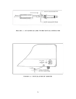
Instructions for installing the phones plug on the speaker cable are illustrated in Figure 1-3 (page
6). After wiring the connector, insert in Phones/SPK jack.
-3-
Summary of Contents for SX-190
Page 1: ......
Page 7: ...FIGURE 1 3 ATTACHING CABLE TO PHONE PLUG CONNECTOR FIGURE 1 4 INSTALLATION OF GROUND 6 ...
Page 17: ... 16 ...
Page 22: ...SCHEMATIC DIAGRAM OF RF AMP 21 ...
Page 23: ...SCHEMATIC DIAGRAM OF BUFFER AMP SCHEMATIC DIAGRAM OF CALIBRATOR 22 ...
Page 24: ...SCHEMATIC DIAGRAM OF VFO SECTION 23 ...
Page 25: ...SCHEMATIC DIAGRAM OF I F AMP SECTION 24 ...
Page 26: ...SCHEMATIC DIAGRAM OF POWER SUPPLY 25 ...
Page 29: ......
Page 30: ......
Page 31: ......

