Not for
Reproduction
20 ALLMAND.COM
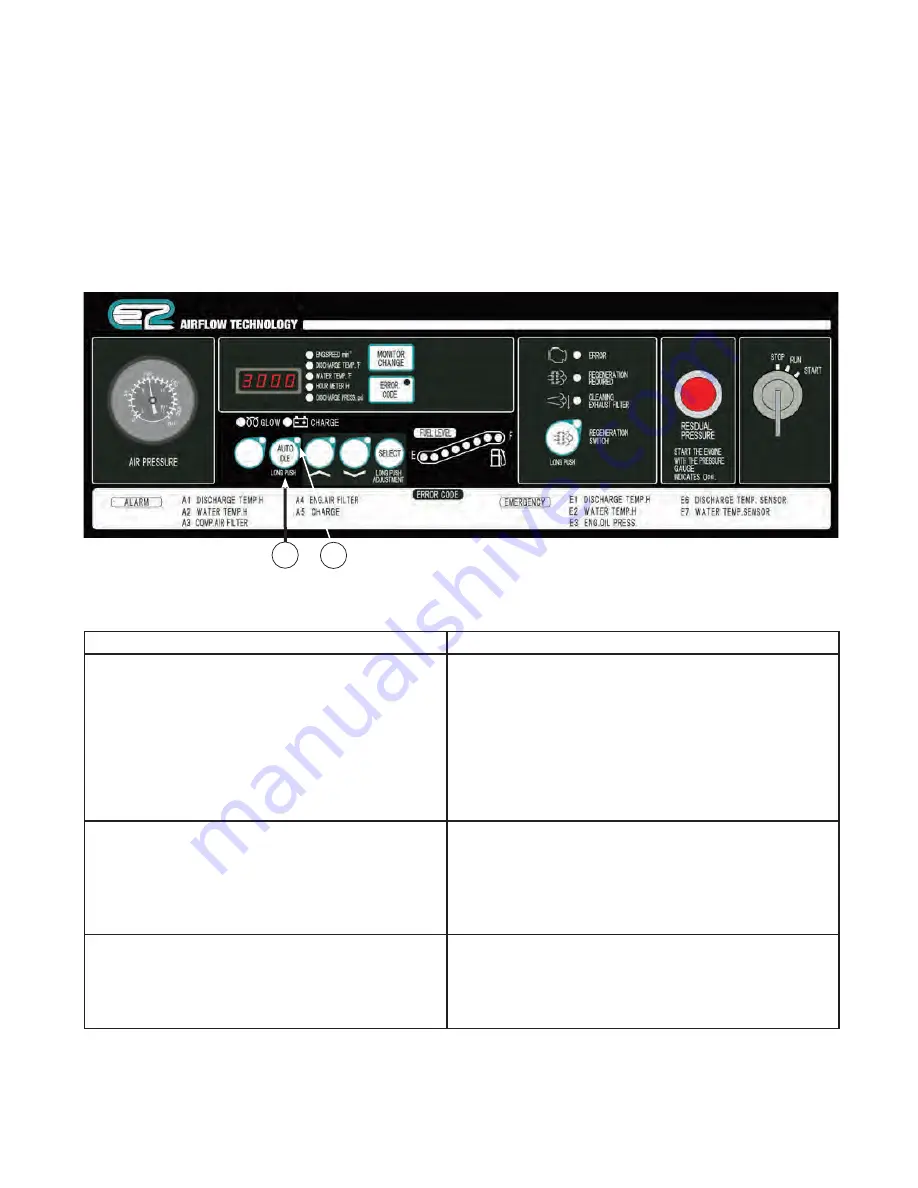
AUTO IDLE control (Purge Control)
This model is equipped with auto idle control operation
mode. This operation mode is recommended when
minimal continuous air consumption is required, and
when minimum power consumption under unloaded
operation is required.
To select auto idle control:
1. During operation, push and hold the auto idle
switch (
A
) until the auto idle indicator lamp (
B
)
goes on, then release switch.
2. Fully close service valve.
3. To stop this operation mode, push auto idle
switch until the lamp (
B
) goes out.
A
B
Function of AUTO IDLE Control (Purge Control)
Conditions of Auto Idle Lamp
First engine speed drops to the minimum speed
by pressure regulator, owing to reduction of air
consumption. Later the air consumption is reduced
further, the unloader valve gradually closes and
intake negative pressure increases. In this stage,
the pressure sensor detects the intake negative
pressure. Then when the intake negative pressure
becomes higher than the set pressure, the “AUTO
IDLE” lamp flickers at short intervals.
Lamp flickers at short intervals.
When this condition continues for a certain time,
the solenoid valve functions to start purge mode
operation. Consequently, the pressure inside
separator receiver tank drops and reduces the power
of compressor air end. In this stage, the lamp “AUTO
IDLE” flickers at longer intervals.
Lamp flickers at longer intervals.
Next, when the pressure for load down to the purge
releasing pressure owing to the increase of air
consumption, the solenoid valve operation gets
“OFF” and it is transferred to normal operation. In this
stage, the lamp “AUTO IDLE” goes on.
Lamp goes on.
Summary of Contents for 185 CFM
Page 8: ...N o t f o r R e p r o d u c t i o n 8 ALLMAND COM L B C F A K G E D J H I N M ...
Page 35: ...N o t f o r R e p r o d u c t i o n 35 Data Adjustment Procedure ...
Page 37: ...N o t f o r R e p r o d u c t i o n 37 ...
Page 38: ...N o t f o r R e p r o d u c t i o n 38 ALLMAND COM ...
Page 39: ...N o t f o r R e p r o d u c t i o n 39 Wiring Diagram ...
Page 41: ...N o t f o r R e p r o d u c t i o n 41 Air Piping Compressor Oil Piping ...


