28 ALLMAND.COM
Change Engine Oil Filter
(For part number, see Replacement Parts)
1. Remove drain plug (
A
) and drain the oil condensed
in filter case (
B
).
2. Remove filter case by loosening center bolt (
C
) and
pull out element (
D
).
3. Replace all the O-rings (
E
,
F
,
G
) with new ones
(which are used for filter case, center bolt and drain
plug). Then install a new filter element in the filter
case.
4. Thinly coat O-ring (
E
) with engine oil and install filter
case by screwing in center bolt (
C
). Tighten to 33
lb-ft (44 Nm).
5. Install drain plug into center bolt. Tighten to 18 lb-ft
(25 Nm).
A
B
D
E
F
C
G
Check GFCI Receptacles
WARNING
• Test the GFCI receptacle before each use.
• In case the GFCI has tripped due to the hazard of
ground fault currents, investigate the cause and
correct it.
Regularly check GFCI operation for safety.
1. Unplug all appliances from the generator.
2. Start the engine.
3. Turn each single-phase and three-phase breaker
ON.
4. Press the TEST BUTTON (
H
):
• The RESET BUTTON (
I
) should extend with a
click.
• If the RESET BUTTON does not extend, contact
your authorized dealer.
5. Press the RESET BUTTON.
6. If the RESET BUTTON extends during operation:
• Unplug all appliances from the GFCI protected
receptacle.
• Press the RESET BUTTON:
IF THE GFCI CANNOT BE RESET:
• The GFCI is faulty. Contact your nearest dealer.
IF THE GFCI RESETS PROPERLY:
• Check the appliance or the power cord.
I
H
Check Insulation Resistance
WARNING
• Insulation resistance should be regularly checked or
measured with a 500V insulation resistance meter.
If it is reduced to lower than 1MΩ, it could cause an
electrical leakage or a fire.
1. Remove the load side cable from the output
terminal board.
2. Remove the grounding terminal from output terminal
plate “N” and “GROUND”, out of the grounding
position of the unit.
3. Remove the AVR connector (
J
) inside the generator
control panel.
4. Switch ON the three-phase breaker, measure each
insulation resistance between the terminals L1. L2.
L3 terminal and bonnet (
K
).
5. If insulation resistance value measured is found
more than 1MΩ, it is good. If lower, contact your
authorized dealer.
NOTE: For improvement of insulation resistance,
wipe and clean dust and dirt from around output
terminals, circuit breaker, generator body outlet port
and receptacles.
6. After checking and confirming that insulation
resistance is proper, reestablish all connections.
Go
to
Discount-Equipment.com
to
order
your
parts
Summary of Contents for Maxi-Power MP65-8B1
Page 8: ...7 I A H B E G C F D K J G o to Discount Equipm ent com to order your parts ...
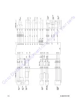
Page 39: ...38 ALLMAND COM Wiring Diagram Generator G o to Discount Equipm ent com to order your parts ...
Page 40: ...39 Engine G o to Discount Equipm ent com to order your parts ...
Page 41: ...40 ALLMAND COM G o to Discount Equipm ent com to order your parts ...
Page 44: ...43 Addendum B Tire Safety Information G o to Discount Equipm ent com to order your parts ...


