


Español - 11 / 36
6-1622396 - rev. 3 - 21/09/2021
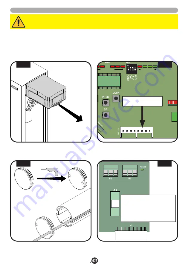
5.3 INSTALACIÓN CON KIT LED (OPCIONAL) - SÓLO PARA 4 METROS
1.
Extraiga la caja del controlador y quite la tapa desenroscando los tornillos adecuados (Fig.13).
2.
Instalar la tarjeta de interfaz LED en el asiento dedicado (en la versión BOOMY 4 LED la tarjeta ya está instalada) (Fig.14).
3.
Perforar dos agujeros de ø 6mm en el tapón negro de plástico que cubre el fondo de la barrera (Fig.15).
4.
Hacer pasar los cables de alimentación de los led a través de los agujeros recién hechos, a través del pasacables del armario
y a través del pasacables del box de la centralita.
5.
Conecte las tiras LED a la tarjeta LED (Fig.16).
ATENCIÓN!
Asegúrese de que la tarjeta no se enciende antes de hacer los enlaces.
G
R +24
G
R +24
Descripción:
G
LED canal VERDE
R
LED canal ROJO
+24
Alimentación LED +24Vdc
PF1
Fusible T 1A
J1
Conector de acoplamiento
1
LED RADIO
FUSE 1
FUSE 2
J2
J1
J3
2
3
4
5
6
7
8
9 10
11 12 13 14 15 16 17
20 21
LED STATUS
LED STATUS
J4
CONECTOR TARJETA
DE INTERFAZ LED
2 x Ø 6mm
FIG. 13
FIG. 14
FIG. 15
FIG. 16
Summary of Contents for 12007336
Page 15: ...Italiano 15 36 6 1622396 rev 3 21 09 2021 45 45 1 2 3 1 2 3 FIG 27 FIG 28...
Page 51: ...English 15 36 6 1622396 rev 3 21 09 2021 45 45 1 2 3 1 2 3 FIG 27 FIG 28...
Page 87: ...Fran ais 15 36 6 1622396 rev 3 21 09 2021 45 45 1 2 3 1 2 3 FIG 27 FIG 28...
Page 123: ...Espa ol 15 36 6 1622396 rev 3 21 09 2021 45 45 1 2 3 1 2 3 FIG 27 FIG 28...
Page 159: ...Nederlandse 15 36 6 1622396 rev 3 21 09 2021 45 45 1 2 3 1 2 3 FIG 27 FIG 28...


